Advertisement
Quick Links
Advertisement

Related Manuals for Ranger design Max Rack


Summary of Contents for Ranger design Max Rack
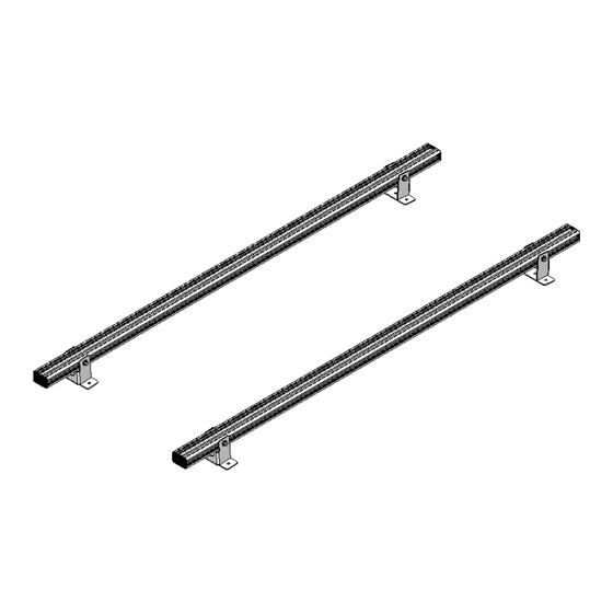
- Page 1 INSTALLATION GUIDE 18-U1806 Max Rack Crossbar ( Max Rack )
-
Page 2: Order Of Operation
ORDER OF OPERATION MAX RACK SINGLE SIDE MAX RACK DOUBLE SIDE 18-U1806 18-U1810 18-U1815 OPTIONAL: Applicable only for Max Rack Double Side. MOUNTING TRACK 18-U1807... -
Page 3: Phase 1 - Assembly
REQUIRED ITEMS FOR COMPLETE MAX RACK NOTE: Use Sawhorses if possible, or use the box as a flat protective surface on the ground. q Cordless Impact q Ratchet q Tape Measure q Marker q Ladder q 1/2" Wrench q 1/2" Socket... - Page 4 PHASE 1 – ASSEMBLY 1.2 MAX RACK PREPARATION 1.2.1 Pull one Crossbar on the box 18-U1806 and put the Crossbar on the table. “You have successfully completed Operation 1 Max Rack Crossbar! Open the passenger side mechanism (18-U1810) box to continue assembling the Max Rack Thank you for doing business with us.”...
- Page 5 INSTALLATION GUIDE MAX RACK DOUBLE SIDE MAX RACK SINGLE SIDE 18-U1810 Max Rack Passenger Side 39" Drop Height From The Roof 79-964...
- Page 6 ORDER OF OPERATION MAX RACK SINGLE SIDE MAX RACK DOUBLE SIDE 18-U1806 18-U1810 18-U1815 OPTIONAL: Applicable only for Max Rack Double Side. MOUNTING TRACK 18-U1807...
- Page 7 Phase 2 - Ladder Installation q 2.1 Extension Ladder Installation......................q 2.2 Step Ladder Installation........................REQUIRED ITEMS FOR COMPLETE MAX RACK NOTE: Use Sawhorses if possible, or use the box as a flat protective surface on the ground or table. q Cordless Impact...
- Page 8 PHASE 1 – ASSEMBLY 1.1 SETUP 1.1.1 Unpack components; compare with the bill of materials. 10-560 × 25.5" 10-560 × 34" 18-4010 18-4008 18-4005 18-193 18-192 18-4002 18-4013 18-4012 18-207 18-167 18-010 18-4001 18-009 1.1.2 Verify all parts are present. Item No.
- Page 9 1.1.3 Fastener kits. 94-0810 Fastener Assembly Ball Stud 1× 3/4" # 40-665 Zinc Plated 1× #40-665 Ball Stud 3/4" #98-117 Flat Washer 5/16" #98-117 Flat Washer 5/16" #94-111 Lock Nut 5/16" Hex Bolt 5× 5/16" - 18 × 2" # 90-225 SS304 5×...
- Page 10 PHASE 1 – ASSEMBLY 1.2 FRONT CROSSBAR ASSEMBLY 1.2.1 Attach carriage bolts to the insert plate. 18-193 18-192 FASTENERS USED 7× #90-491 Carriage Bolt 1" 1.2.2 Slide the insert plate to the crossbar w/ shaft support bracket. NOTE: Repeat this step on the other side of the crossbar if you are assembling a double sided rack.
- Page 11 1.2.3 Attach the 2 feet to the crossbar. FOOT PLACEMENT GUIDE VEHICLE DIMENSION ( A ) 7" issan 10" 6 - 1/2" printer high roof standard roof 8 - 7/8" ransit 7 - 1/16" romaster 18-187 18-187 TOOLS q Cordless Impact q 1/2"...
- Page 12 1.2.4 Attach the passenger side front mechanism to the crossbar using the insert plate w/ 5 holes, then add flat washers and lock nuts to the shaft support bracket. 18-4002 TIPS: • Use a box to support the mechanism to facilitate assembly.
- Page 13 1.2.5 Slide the pivot bar with front linkage and spacer through the shaft support bracket and arm, then attach the pivot bar to the arm. NOTE: Line up the hole of the front pivot bar to the hole of the arm. 18-4012 SPACER haft support braCket...
- Page 14 1.2.6 Attach the gas spring combo to the ball studs. NOTE: Gas spring combo will have "18-167" printed on it. TIPS: Loosen the ball stud, attach the combo, then retighten the ball stud. 18-167 1.2.7 • Attach one small hook and front ladder retainer to the front mechanism. •...
- Page 15 1.2.8 Attach the long hook to the crossbar, facing to the small hook. NOTE: If you are using a step ladder, the hook position will need to be adjusted. (Follow the mounting track installation guide). end cap 18-4008 t attaCh if you assembling double sided raCk end cap NOTE: Use the insert plate w/ 2 holes.
- Page 16 PHASE 1 – ASSEMBLY 1.3 REAR CROSSBAR ASSEMBLY 1.3.1 Attach carriage bolts to the insert plate. 18-193 18-192 FASTENERS USED 7× #90-491 Carriage Bolt 1" 1.3.2 Slide the insert plate to the crossbar w/ shaft support bracket. NOTE: Repeat this step on the other side of the crossbar if you are assembling a double sided rack.
- Page 17 1.3.3 Attach the 2 feet to the crossbar. FOOT PLACEMENT GUIDE VEHICLE DIMENSION ( A ) 7" issan 10" 6 - 1/2" printer high roof standard roof 130" 8 - 7/8" ransit 148" & 148" 8 - 7/8" ransit 118" 7 - 1/16"...
- Page 18 1.3.4 Attach the passenger side rear mechanism to the crossbar using the insert plate w/ 5 holes, then add flat washers and lock nuts to the shaft support bracket. TIPS: • Use a box to support the mechanism to facilitate assembly. NOTE: Front &...
- Page 19 1.3.5 Attach the gas spring to the rear linkage. NOTE: Gas spring will have "18-010" printed on it. 18-010 18-4013 TOOLS FASTENERS USED q Cordless Impact 1× ( 17 ft • lbs ) q 1/2" Socket q 1/2" Wrench #40-665 Ball Stud 3/4" #98-117 Flat Washer 5/16"...
- Page 20 1.3.6 Slide the pivot bar with rear linkage through the arm and shaft support bracket, then attach the pivot bar to the arm. 2 - 5/8" 5" se this hole NOTE: Holes should be on top. FASTENERS USED TOOLS 1× q 1/2"...
- Page 21 1.3.7 Slide the passenger side damper kit to the pivot bar, then attach the passenger side damper kit to the pivot bar. assenger amper SPACER lot for the handle ivot FASTENERS USED TOOLS 1× q Cordless Impact ( 17 ft • lbs ) q 1/2"...
- Page 22 1.3.8 Attach ball stud to the passenger side damper kit and rear mechanism frame. TOOLS q Cordless Impact q 1/2" Socket q 1/2" Wrench ×2 FASTENERS USED 2× ( 17 ft • lbs ) #40-665 Ball Stud 3/4" #98-117 Flat Washer 5/16" #98-117 Flat Washer 5/16"...
- Page 23 1.3.9 Attach the damper and gas spring to the ball stud. NOTE: amper ou Can Compress 18-009 18-010 TIPS: Loosen the ball stud, attach the Gas spring, then retighten the ball stud. 18-U1810 Installation Guide | REV. C3 | Page 19 For technical support, contact us at 1-800-565-5321...
- Page 24 1.3.10 • Attach the long hook to the crossbar, facing to the small hook. • Cut the track plug to length and install. NOTE: If you are using a step ladder, the hook position will need to be adjusted. (Follow the mounting track installation guide). 10-560 ×...
- Page 25 1.4 FOR ASSEMBLY WITH OVERHEAD LIFT 1.4.1 Attach the ends of the front and rear bars to the center tube. NOTE: Skip this step if you don’t have an overhead lift or if you have a Max Rack double side. Crossbar Center to Center distanCe se this holes of the Center bar 65"...
- Page 26 PHASE 1 – ASSEMBLY 1.5 ASSEMBLY VALIDATION 1.5.1 Validate your assembly to ensure smooth operation of your Max Rack. NOTE: Front & Rear Should have same dimension. 1.5" eCommended 1.5" eCommended 18-U1810 Installation Guide | REV. C3 | Page 22...
- Page 27 PHASE 2 – LADDER INSTALLATION 2.1 EXTENDED LADDER INSTALLATION STEP • Place the Max Rack in the down position. • Load the ladder onto the Max Rack. NOTE: These conditions must be respected: • The arm socket and the ladder cannot extend beyond the rear bumper of the vehicle.
- Page 28 PHASE 2 – LADDER INSTALLATION 2.2 STEP LADDER INSTALLATION NOTE: These conditions must be respected: • The arm socket and the ladder cannot extend beyond the rear bumper of the vehicle. • The center of the ladder must be behind the front hook when the ladder is loaded. 15"...
- Page 29 “You have successfully completed Operation 2 Max Rack Passenger Side Mechanism! Open the driver side mechanism (18-U1815) box or follow the Install Guide of the mounting track to install the Max Rack on your vehicle. Thank you for doing business with us.” cs@rangerdesign.com For any feedback or suggestions you might have, please contact: 18-U1810 Installation Guide | REV.
- Page 30 INSTALLATION GUIDE MAX RACK DOUBLE SIDE MAX RACK SINGLE SIDE 18-U1815 Max Rack Driver Side 39" Drop Height From The Roof 79-963...
-
Page 31: Order Of Operation
ORDER OF OPERATION MAX RACK SINGLE SIDE MAX RACK DOUBLE SIDE 18-U1806 18-U1810 18-U1815 OPTIONAL: Applicable only for Max Rack Double Side. MOUNTING TRACK 18-U1807... - Page 32 Phase 2 - Ladder Installation q 2.1 Extension Ladder Installation......................q 2.2 Step Ladder Installation........................REQUIRED ITEMS FOR COMPLETE MAX RACK NOTE: Use Sawhorses if possible, or use the box as a flat protective surface on the ground or table. q Cordless Impact...
- Page 33 PHASE 1 – ASSEMBLY 1.1 SETUP 1.1.1 Unpack components; compare with the bill of materials. 10-560 × 25.5" 10-560 × 34" 18-4010 18-4008 18-4505 18-193 18-192 18-4502 18-4513 18-4512 18-207 18-167 18-010 18-4501 18-009 1.1.2 Verify all parts are present. Item No.
- Page 34 1.1.3 Fastener kits. 94-0815 Fastener Assembly Ball Stud 1× 3/4" # 40-665 Zinc Plated 1× #40-665 Ball Stud 3/4" #98-117 Flat Washer 5/16" #98-117 Flat Washer 5/16" #94-111 Lock Nut 5/16" Hex Bolt 5× 5/16" - 18 × 2" # 90-225 SS304 5×...
- Page 35 PHASE 1 – ASSEMBLY 1.2 FRONT CROSSBAR ASSEMBLY 1.2.1 Attach carriage bolts to the insert plate. 18-193 18-192 FASTENERS USED 7× #90-491 Carriage Bolt 1" 18-U1815 Installation Guide | REV. C3 | Page 6 For technical support, contact us at 1-800-565-5321...
- Page 36 NOTE: Skip this step if you slide 2 shaft support bracket for double sided rack already. 1.2.2 • Remove the driver side feet, then slide the insert plate to the crossbar w/ shaft support bracket. • Reinstall the feet after slinding the plate w/ shaft support bracket. FOOT PLACEMENT GUIDE VEHICLE DIMENSION ( A )
- Page 37 1.2.3 Attach the driver side front mechanism to the crossbar using the insert plate w/ 5 holes, then add flat washers and lock nuts to the shaft support bracket. 18-4502 TIPS: • Use a box to support the mechanism to facilitate assembly.
- Page 38 1.2.4 Slide the pivot bar with front linkage and spacer through the shaft support bracket and arm, then attach the pivot bar to the arm. NOTE: Line up the hole of the front pivot bar to the hole of the arm. haft support braCket 18-4512 18-004...
- Page 39 1.2.5 Attach the gas spring combo to the ball studs. NOTE: Gas spring combo will have "18-167" printed on it. TIPS: Loosen the ball stud, attach the combo, then retighten the ball stud. 18-167 1.2.6 • Attach one small hook and front ladder retainer to the front mechanism. •...
- Page 40 1.2.7 Attach the long hook to the crossbar, facing to the small hook. NOTE: If you are using a step ladder, the hook position will need to be adjusted. (Follow the mounting track installation guide). end cap end cap 2 - 1/2" TOOLS q Cordless Impact q 1/2"...
- Page 41 PHASE 1 – ASSEMBLY 1.3 REAR CROSSBAR ASSEMBLY 1.3.1 Attach carriage bolts to the insert plate. 18-193 18-192 FASTENERS USED 7× #90-491 Carriage Bolt 1" 18-U1815 Installation Guide | REV. C3 | Page 12 For technical support, contact us at 1-800-565-5321...
- Page 42 NOTE: Skip this step if you slide 2 shaft support bracket for double sided rack already. 1.3.2 • Remove the driver side feet, then slide the insert plate to the crossbar w/ shaft support bracket. • Reinstall the feet after slinding the plate w/ shaft support bracket. FOOT PLACEMENT GUIDE VEHICLE DIMENSION ( A )
- Page 43 1.3.3 • Slide 3 channel nuts into the top channel of the crossbar. • Attach the driver side rear mechanism to the crossbar with washer plate using the 3 channel nuts. TIPS: • Use a box to support the mechanism to facilitate assembly.
- Page 44 1.3.4 Attach the gas spring to the rear linkage. NOTE: Gas spring will have "18-010" printed on it. 18-010 18-4513 TOOLS FASTENERS USED q Cordless Impact 1× ( 17 ft • lbs ) q 1/2" Socket q 1/2" Wrench #40-665 Ball Stud 3/4" #98-117 Flat Washer 5/16"...
- Page 45 1.3.5 Slide the pivot bar with rear linkage through the arm and shaft support bracket, then attach the pivot bar to the arm. 2 - 5/8" 5" se this hole 5" NOTE: Holes should be on top. FASTENERS USED TOOLS 1×...
- Page 46 1.3.6 Slide the driver side damper kit to the pivot bar, then attach the driver side damper kit to the pivot bar. river amper lot for the handle ivot FASTENERS USED TOOLS 1× q Cordless Impact ( 17 ft • lbs ) q 1/2"...
- Page 47 1.3.7 Attach ball stud to the driver side damper kit and rear mechanism frame. TOOLS q Cordless Impact q 1/2" Socket q 1/2" Wrench ×2 FASTENERS USED 2× ( 17 ft • lbs ) #40-665 Ball Stud 3/4" #98-117 Flat Washer 5/16" #98-117 Flat Washer 5/16"...
- Page 48 1.3.8 Attach the damper and gas spring to the ball stud. NOTE: amper ou Can Compress TIPS: Loosen the ball stud, attach the Gas spring, then retighten the ball stud. 18-009 18-010 18-U1815 Installation Guide | REV. C3 | Page 19 For technical support, contact us at 1-800-565-5321...
- Page 49 1.3.9 • Attach the long hook to the crossbar, facing to the small hook. • Cut the track plug to length, then install. NOTE: If you are using a step ladder, the hook position will need to be adjusted. (Follow the mounting track installation guide). ut the traCk plug to length then install end cap...
- Page 50 1.4 FOR ASSEMBLY WITH OVERHEAD LIFT 1.4.1 Attach the ends of the front and rear bars to the center tube. NOTE: Skip this step if you don’t have an overhead lift or if you have a Max Rack double side. Crossbar Center to Center distanCe se this holes of the Center bar 65"...
- Page 51 PHASE 1 – ASSEMBLY 1.5 ASSEMBLY VALIDATION 1.5.1 Validate your assembly to ensure smooth operation of your Max Rack. NOTE: Front & Rear Should have same dimension. 1.5" eCommended 1.5" eCommended 18-U1815 Installation Guide | REV. C3 | Page 22...
- Page 52 PHASE 2 – LADDER INSTALLATION 2.1 EXTENDED LADDER INSTALLATION STEP • Place the Max Rack in the down position. • Load the ladder onto the Max Rack. NOTE: These conditions must be respected: • The arm socket and the ladder cannot extend beyond the rear bumper of the vehicle.
- Page 53 PHASE 2 – LADDER INSTALLATION 2.2 STEP LADDER INSTALLATION NOTE: These conditions must be respected: • The arm socket and the ladder cannot extend beyond the rear bumper of the vehicle. • The center of the ladder must be behind the front hook when the ladder is loaded. 15"...
- Page 54 “You have successfully completed Operation 3 Max Rack Driver Side Mechanism! Open the mounting track box, then follow the Install Guide of the mounting track to install the Max Rack on your vehicle. Thank you for doing business with us.” cs@rangerdesign.com For any feedback or suggestions you might have, please contact: 18-U1815 Installation Guide | REV.
- Page 55 INSTALLATION GUIDE 18-U0034 MOUNTING TRACKS Ram ProMaster ( 159" Extended Wheelbase, High Roof )
- Page 56 ORDER OF OPERATION MAX RACK SINGLE SIDE MAX RACK DOUBLE SIDE 18-U1806 18-U1810 18-U1815 OPTIONAL: Applicable only for Max Rack Double Side. MOUNTING TRACK 18-U1807...
- Page 57 2.2 Max Rack installation.......................... Phase 3 - Adjustment q 3.1 Adjustment for Max Rack........................10 REQUIRED ITEMS FOR COMPLETE MAX RACK NOTE: Use Sawhorses if possible, or use the box as a flat protective surface on the ground or table.
- Page 58 PHASE 1 – ASSEMBLY 1.1 SETUP 1.1.1 Unpack components; compare with the bill of materials. 10-716 10-713 10-343 10-342 70-015 1.1.2 Verify all parts are present. Item No. Description Qty. 10-716 Mounting Track 88.5" Long 10-713 Mounting Track 59" Long 10-342 Roof Clamp 10-343...
-
Page 59: Phase 2 - Installation
1.1.3 Identify the Assembly and Installation fastener bags. 96-0034 Fastener Assembly Hex Nut 16× 5/16"-18 # 94-105 SS316wax 16× #94-105 Hex Nut Flat Washer #98-123 Lock Washer 16× # 98-117 5/16" OD, 3/4" SS18-8 #98-117 Flat Washer Roof Clamp ( 8 ) Lock Washer 16×... - Page 60 2.1.2 Slide 1 stud plate on each mounting track. Ront 18-191 FRom cRossbaR box 2.1.2 Install the mounting tracks onto the roof of the van. NOTE: Notice the orientations of the roof clamps, top roof clamps and the mounting tracks. The top roof clamp should lay flat on the roof clamp and not slant.
- Page 61 2.2 MAX RACK INSTALLATION 2.2.1 Position the Max Rack ( minimum two persons ) on the vehicle so that the feet are on the tracks. NOTE: If you do not have an overhead lift, lift the front crossbar onto the roof first then the rear crossbar.
- Page 62 2.2.2 Attach the ends of the front and rear bars to the center tube. cRossbaR centeR to centeR distance se this holes oF the centeR baR 65" se this holes oF the centeR baR 65" excePt FoR 65" 65" FoR gReateR than FASTENERS USED TOOLS 2×...
- Page 63 2.2.3 • Align the arm socket to the rear bumper of the vehicle. • Attach all the feet w/ shim to the mounting tracks. NOTE: These conditions must be respected: • The arm socket and the ladder cannot extend beyond the rear bumper of the vehicle. •...
- Page 64 2.2.4 Before tightening the feet to the mounting track make sure that the 2 crossbar is parallel. cRossbaR centeR to centeR distance Recommended set uP 65" cRossbaR centeR to centeR distance Recommended set uP 65" Recommended set VEHICLE CROSSBAR CENTER TO CENTER DISTANCE LADDER SIZE 65"...
- Page 65 PHASE 3 – ADJUSTMENT 3.1 ADJUSTMENT FOR MAX RACK 3.1.1 • Place the Max Rack in the down position. • Load the ladder onto the Max Rack. NOTE: These conditions must be respected: • The arm socket and the ladder cannot extend beyond the rear bumper of the vehicle.
- Page 66 STEP LADDER INSTALLATION NOTE: These conditions must be respected: • The arm socket and the ladder cannot extend beyond the rear bumper of the vehicle. • The center of the ladder must be behind the front hook when the ladder is loaded. lush extend 8' STEP LADDER...
- Page 67 NOTE: • Ensure that everything is safely assembled and fastened. • With the ladder locked, operate your Max Rack a few times, while carefully observing the moving parts. “Congratulations, you have successfully installed your Mounting Tracks and your completed Rack on your vehicle! Thank you for doing business with us.”...
Need help?
Do you have a question about the Max Rack and is the answer not in the manual?
Questions and answers