Table of Contents
Advertisement
Quick Links
Advertisement
Table of Contents

Related Manuals for SIGLENT SDS7000A Series


Summary of Contents for SIGLENT SDS7000A Series
- Page 1 SDS7000A Series Digital Storage Oscilloscope Quick Start EN01A...
-
Page 3: Copyright Information
Declaration SIGLENT products are protected by patent law in and outside of P.R.C. SIGLENT reserves the right to modify or change parts of or all the specifications or pricing policies at the company’s sole decision. Information in this publication replaces all previously corresponding material. -
Page 4: Table Of Contents
Safety Terms and Symbols........................... 4 General Care and Cleaning ......................... 4 General Inspection ............................5 Mechanical Dimensions ..........................6 Panel Introduction ............................7 Quick Start ..............................9 User Interface ............................. 12 Basic Operations ............................17 Advanced Analysis Features ........................25 SDS7000A Series Quick start... -
Page 5: General Safety Summary
Avoid Exposed Circuits and Components Do not touch exposed contacts or components when the instrument's power is on. Use Only the Specified Fuse Do Not Operate Without Covers Do not operate the instrument with covers or panels removed. SDS7000A Series Quick start... -
Page 6: Safety Terms And Symbols
To avoid damage to the surface of the instrument and probe, please do not use any corrosive liquid or chemical cleansers. Make sure that the instrument is completely dry before restarting it to avoid potential short circuits or personal injury. SDS7000A Series Quick start... -
Page 7: General Inspection
The consigner or carrier will be responsible for damages to the instrument resulting from shipment. SIGLENT will not provide free maintenance or replacement if the instrument has been damaged in shipment. ... -
Page 8: Mechanical Dimensions
Mechanical Dimensions Front View Side View SDS7000A Series Quick start... -
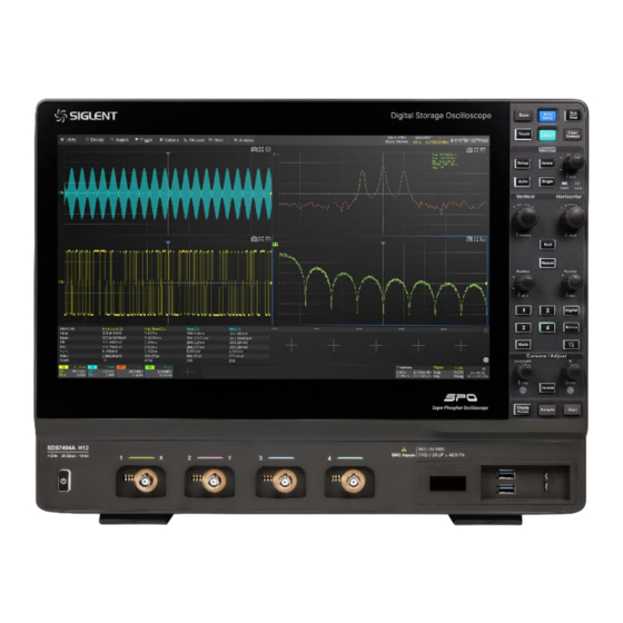
Page 9: Panel Introduction
Touch Screen Display pass / fail signal Knobs and buttons Ext Trigger Input Power Standby Button OCXO Module (Assembled and calibrated in factory only) Supporting Legs USB 2.0 Device. Connect with a PC for remote control Handle SDS7000A Series Quick start... - Page 10 2x 1000M LAN Ports 4x USB Host 3.1 Gen 1 Ports DP 1.2 Video output HDMI 1.4 Video output COM. Only used for internal debug DVI-D Video output Audio Line In , Line Out , Mic In SDS7000A Series Quick start...
-
Page 11: Quick Start
The reference is a square wave and can be output from the 10 MHz Out port for synchronizing other instruments. To set the reference clock by following the steps: Utility > Menu > I/O > Clock Source . SDS7000A Series Quick start... - Page 12 Click here to save the waveform data as a CSV file and download it to the local computer Click here to download the mini-tool for converting binary files to CSV Click here to perform a firmware upgrade SDS7000A Series Quick start...
- Page 13 Check the displayed waveforms and compare them with the following figure. Under Compensated Over Compensated Correctly Compensated Use a nonmetallic flat-head screwdriver to adjust the low-frequency compensation adjustment hole on the probe until the waveform matches the “ Compensated Correctly ” waveform above. SDS7000A Series Quick start...
-
Page 14: User Interface
6. Probe Attenuation Factor Timebase and Trigger Descriptor Boxes 1. Trigger delay 2. Horizontal scale 1. Trigger source 2. coupling (timebase) 3. Trigger mode 4. Trigger level 3. # Samples 4. Sample Rate 5. Trigger type 6. Trigger slope SDS7000A Series Quick start... - Page 15 If the expected value is 65 ns, input “65” on the virtual keypad, and then choose the unit n to complete the operation. On the virtual keypad, clicking the button , and Default quickly sets the parameter to its maximum, minimum and default values. SDS7000A Series Quick start...
- Page 16 Draw a rectangular box to create a zone or a histogram region. At the beginning of the gesture keep the angle close to 45° so it can be recognized as the drawing box gesture SDS7000A Series Quick start...
- Page 17 Floating mode. If the window has been in floating mode, the icon will become . At this time click it to retore to fixed mode. A floating window can be dragged to any location in the display, including the extended display. SDS7000A Series Quick start...
- Page 18 All the knobs on the front panel are multi-function. They can be pushed as well as rotated. Pushing a knob quickly recalls a specific function, which is indicated by the silkscreen near the knob. Choosing the Language Utility > Menu > System settings > Language . SDS7000A Series Quick start...
-
Page 19: Basic Operations
Copy the setting of the current channel to another channel Quickly select the current channel as the source of a specified operation (Trigger, FFT, Measure, Cursor, Search, DVM, and Counter) Disable the channel 10. Hide the trace SDS7000A Series Quick start... - Page 20 ▲ to increase and ▼ to decrease the trigger delay Set the trigger delay to zero Set the trigger point to the left part of the screen Set the trigger point to the right part of the screen Open the Acquire dialog box SDS7000A Series Quick start...
- Page 21 Select the Acq mode Select the acquisition mode (Normal / Peak / Average / Hi-Res) Select the Memory Management mode (Auto, Fixed Sample Rate, and Fixed Memory) Select the maximum memory depth Enter the sequence menu XY mode on/off SDS7000A Series Quick start...
- Page 22 Enable / disable Noise Rejection. When Noise Reject is on, the trigger hysteresis is increased, so the noise immunity of the trigger circuit is better. As a compromise, the trigger sensitivity degrades Set the Zone Trigger SDS7000A Series Quick start...
- Page 23 7. Tools including Trend, Track, and specified basic measurement parameters Measure Cursor of the selected channel. In "Advanced" 8. Turn on or off statistics mode, the measurement parameters can be added one by one as needed SDS7000A Series Quick start...
- Page 24 Math and Decoding functions and can provide more accurate measurements than a reference waveform. Click + at the bottom and select M1 ~ M4 to set a memory trace. SDS7000A Series Quick start...
- Page 25 Perform Utility > Screenshot or pressing button (If the function of the button has been defined as “screenshot”) to capture the screen to a .bmp\ .jpg\ .png picture. The file will be saved in the path specified in the File Manager. SDS7000A Series Quick start...
- Page 26 Follow the steps below to install a software option (see the datasheet for details) after purchasing it and obtaining the Option Key: Utility > Menu > Software Options . Select the correct Option Type. Input the option key in the text box. Click Install and then restart the oscilloscope. SDS7000A Series Quick start...
-
Page 27: Advanced Analysis Features
The DVM (Digital Voltage Meter) function can be used to measure parameters such as DC and AC amplitudes. DVM is asynchronous to the acquisition system of the oscilloscope. Data sources for the DVM and the measurement function can be different. SDS7000A Series Quick start... - Page 28 Headquarters: SIGLENT Technologies Co., Ltd Add: Bldg No.4 & No.5, Antongda Industrial Zone, 3rd Liuxian Road, Bao'an District, Shenzhen, 518101, China Tel: + 86 755 3688 7876 Fax: + 86 755 3359 1582 Email: sales@siglent.com Website: int.siglent.com North America: SIGLENT Technologies America, Inc...
Need help?
Do you have a question about the SDS7000A Series and is the answer not in the manual?
Questions and answers