SIGLENT SDS2000X Plus Quick Start Manual
Digital storage oscilloscope
Hide thumbs
Also See for SDS2000X Plus:
- User manual (335 pages) ,
- Service manual (70 pages) ,
- User manual (324 pages)
Table of Contents
Advertisement
Quick Links
Advertisement
Table of Contents

Related Manuals for SIGLENT SDS2000X Plus


Summary of Contents for SIGLENT SDS2000X Plus
- Page 1 SDS2000X Plus Digital Storage Oscilloscope Quick Start QS0102XP_E01B...
-
Page 3: Copyright Information
Declaration SIGLENT products are protected by patent law in and outside of P.R.C. SIGLENT reserves the right to modify or change parts of or all the specifications or pricing policies at the company ’ s sole decision. Information in this publication replaces all previously corresponding material. -
Page 4: Table Of Contents
GENERAL CARE AND CLEANING ....................... 5 GENERAL INSPECTION ..........................6 QUICK START ............................... 7 FRONT OF OSCILLOSCOPE ........................9 BACK OF OSCILLOSCOPE ........................10 PROBE COMPENSATION ........................11 USER INTERFACE ............................. 12 BASIC OPERATIONS ..........................19 SDS2000X Plus Quick Start... -
Page 5: General Safety Summary
Electrostatic Prevention Operate in an electrostatic-protected area environment to avoid damages induced by static discharge. Always ground both the internal and external conductors of the cable to release a static charge before connecting. SDS2000X Plus Quick Start... - Page 6 Indicates potential injury or hazards that may happen. CAUTION Indicates potential damage to the instrument or other property that may happen. Symbols used in this product. These symbols may appear on the product: Hazardous Protective Earth Warning Earth Ground Power Switch Voltage Ground SDS2000X Plus Quick Start...
-
Page 7: General Care And Cleaning
To avoid damage to the surface of the instrument and probe, please do not use any corrosive liquid or chemical cleansers. Make sure that the instrument is completely dry before restarting it to avoid potential short circuits or personal injury. SDS2000X Plus Quick Start... -
Page 8: General Inspection
The consigner or carrier will be responsible for damages to the instrument resulting from shipment. SIGLENT would not provide free maintenance or replacement if the instrument has been damaged in shipment. 2. Inspect the instrument If there are instruments found damaged, defective or failure in electrical and mechanical tests, please contact SIGLENT. -
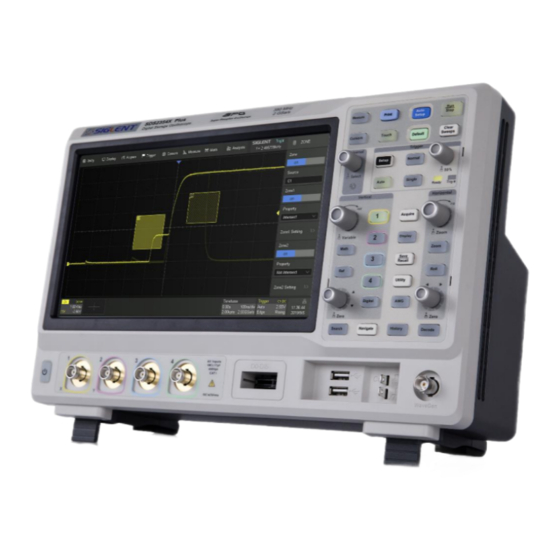
Page 9: Quick Start
Quick Start Front View Top View SDS2000X Plus Quick Start... - Page 10 Connecting to Power Supply The standard power supply for the instrument is 100~240 V, 50/60 Hz or 100~120 V, 400 Hz. Please use the power cord provided with the instrument to connect it to AC power. SDS2000X Plus Quick Start...
-
Page 11: Front Of Oscilloscope
The built-in Waveform Generator is capable of outputting up to 50 MHz frequency. Connect the USB Host Ports to USB storage devices used for data transfer, or USB mouse / keyboard for control. Digital Input Connector receives 16-channel digital signals from the SPL2016 digital probe. SDS2000X Plus Quick Start... -
Page 12: Back Of Oscilloscope
Auxiliary Output outputs the trigger indicator. When Pass / Fail is enabled, outputs the pass / fail signal. External Trigger Input. LAN Port connects to the network for remote control. USB Device connects with a PC for remote control. AC Power Input. Handle. SDS2000X Plus Quick Start... -
Page 13: Probe Compensation
2. Check the displayed waveforms and compare them with the following figure. Under Compensate Over Compensated d Correctly Compensate 3. Use a nonmetallic flat-head screwdriver to adjust the low-frequency compensation adjustment hole on the probe until the waveform matches the “Compensated Correctly” waveform above. SDS2000X Plus Quick Start... -
Page 14: User Interface
Dialog Box is the main area to select the parameters for a chosen specific function. Trigger Delay Indicator locates where the waveform triggers on the horizontal axis. Trigger Level Indicator shows the level where the waveform triggers on the vertical axis. Cursors show where measurement points have been set. SDS2000X Plus Quick Start... - Page 15 Channel index Bandwidth limit indicator Coupling and impedance Volts/div Offset Probe attenuation Timebase and Trigger Descriptor Boxes Trigger delay Time/div # Samples Sample rate Trigger source Trigger coupling Trigger mode Trigger level Trigger type Trigger slope SDS2000X Plus Quick Start...
- Page 16 Scroll bar. When parameters are more than the displayed range, the blue scrollbar will be displayed. By sliding the dialog area up and down, or rolling the mouse wheel, it can scroll to the area not displayed. SDS2000X Plus Quick Start...
- Page 17 To Set Parameters The SDS2000X Plus provides several different ways to set parameters: Switch – sets parameters with two states, such as to enable or disable a function. Touch the switch region to change from one state to the other.
- Page 18 Pinch spread waveform horizontally to re-scale the timebase Drag the waveform up and down to move it on the vertical axis Pinch and spread the waveform vertically to re-scale the vertical gain SDS2000X Plus Quick Start...
- Page 19 Draw a rectangular box to create a zone or a histogram region. At the beginning of the gesture keep the angle close to 45° so it can be recognized as the drawing box gesture SDS2000X Plus Quick Start...
- Page 20 When it is lighted the functionality is enabled Rotate the universal knob to set the value of the activated parameter, or to move the selected cursor. Push to select a different cursor. Choosing the Language > System setting > Language SDS2000X Plus Quick Start...
-
Page 21: Basic Operations
Touch the channel descriptor box and then touch the Off button to disable it. SDS2000X Plus Quick Start... - Page 22 Rotate the knob to adjust the DC offset or vertical position of the channel. Push to set the offset to zero Digital channels on / off Math on / off Reference on / off SDS2000X Plus Quick Start...
- Page 23 Copy the setting of the current channel to another channel Quickly select the current channel as the source of a specified operation (Trigger, FFT, Measure, Cursor, Search, DVM, and Counter) Disable the channel Open the dialog box on the right side SDS2000X Plus Quick Start...
- Page 24 Set the label text. Click to recall the label setting. Users can customize the text and display of the label Quickly apply specified operation (Cursor, Measure, FFT, Search, DVM, Histogram and Mask Test) to the current channel Impedance Units for the channel Deskew Enable/disable invert SDS2000X Plus Quick Start...
- Page 25 Zoom Push to enable horizontal Roll; push again to exit Roll mode. At timebase settings larger than 50ms/div, it is recommended to set the oscilloscope to Roll mode so that the waveform is displayed in real-time SDS2000X Plus Quick Start...
- Page 26 ▲ to increase and ▼ to decrease the trigger delay Set the trigger delay to zero Set the trigger delay to the left part of the screen Set the trigger delay to the right part of the screen Open the Acquire dialog box SDS2000X Plus Quick Start...
- Page 27 Select the maximum memory depth (up to 200 Mpts/ch) Set Sequence mode Select the vertical resolution. When 10-bit is selected, the resolution is enhanced by 4 times, while the bandwidth is downgraded to around 100 MHz SDS2000X Plus Quick Start...
- Page 28 Zoom The SDS2000X Plus supports waveform zoom in the horizontal and vertical directions. Push the Zoom button on the front panel to enable Zoom mode. When the Zoom mode is enabled, Press down the horizontal knob to switch between the main window and zoom window.
- Page 29 Trigger level adjustment -- push to set the level to 50% of the waveform Ready LED, lighted when ready for trigger Trig'd LED, lighted when a trigger event happens Indicators Relative to Trigger Trigger level indicator Trigger delay indicator Trigger delay indicator (outside the screen) SDS2000X Plus Quick Start...
- Page 30 Set trigger coupling mode (DC/AC/LF Reject/HF Reject) Enable/disable Noise Rejection. When Noise Reject is on, the trigger hysteresis is increased, so the noise immunity of the trigger circuit is better. As a compromise, the trigger sensitivity degrades Set the Zone trigger SDS2000X Plus Quick Start...
- Page 31 Math trace Math setup dialog box Selects the trace (F1 or F2) Selects the operator and source (C1~C4, Z1~Z4, F1~F2) SDS2000X Plus Quick Start...
- Page 32 Measurement parameters and statistics display area. If select the mode as “Simple”, the "Simple" parameter area is displayed. Touch the button on the front panel to reset the statistics Measure dialog box SDS2000X Plus Quick Start...
- Page 33 For more information please refer to the User Manual. Push the button to open the cursors setup dialog box Rotate the knob to move the selected cursor; push to select different cursor The display mode of cursors Display mode 1 Display mode 2 SDS2000X Plus Quick Start...
- Page 34 Set the label text of the reference trace Save the specified waveform in to the specified location in The reference waveforms(.ref)can be saved to an external storage device. See the chapter “Save / Recall” for details. SDS2000X Plus Quick Start...
- Page 35 “External”, touch this region to recall the file manager for further operations Quickly Save a Screenshot Push the button on the front panel to save the screenshot as a picture (.bmp/.png/.jpg) to an external storage device. SDS2000X Plus Quick Start...
- Page 36 Whenever the oscilloscope is used in an environment outside 23 ± 5 °C, or when it has been more than one month since the previous calibration, manual calibration is recommended. To perform a self-calibration: Touch Utility > Menu > Do Self Cal > Do Self Cal SDS2000X Plus Quick Start...
- Page 37 Option Key: Utility > Menu > Options ,或 > Options 2. Select the correct Option Type 3. Input the option key in the text box 4. Touch Install and then restart the oscilloscope SDS2000X Plus Quick Start...
- Page 39 DC power supplies, electronic loads and other general purpose test instrumentation. Since its first oscilloscope was launched in 2005, SIGLENT has become the fastest growing manufacturer of digital oscilloscopes. We firmly believe that today SIGLENT is the best value in electronic test & measurement. Headquarters: SIGLENT Technologies Co., Ltd...
Need help?
Do you have a question about the SDS2000X Plus and is the answer not in the manual?
Questions and answers