Advertisement
Quick Links
INSTALLATION INSTRUCTIONS
DESCRIPTION
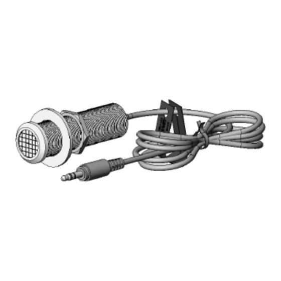
The 490-85 is a CFL (compact fluorescent light) / LCD (liquid crystal display) version of the 490 Micro
Link series IR receivers. It is specifically designed to have greater immunity to high frequency
ballasted CFL and overhead fluorescent type infrared inference and to have exceptional IR reception
range.
These small IR receivers have been designed primarily for mounting in panels, doors, cabinets, etc.
for control of A/V equipment behind closed doors. They may be mounted in walls, ceilings, wall
speakers, etc. - anywhere an inconspicuous appearance is desired. Their high sensitivity allows
placement behind speaker grilles and still receiver IR commands up to 20 feet away.
FEATURES AND SPECIFICATIONS
IR carrier frequency reception bandwidth: 30 to 60 kHz.
IR carrier adjustment: 32 to 56 kHz (allows output carrier frequency to be matched to a
controlled component for optimum performance).
IR reception range: > 50 feet
Dimensions: 2.75" Length x 0.75" DIA. Bezel is 0.90" DIA.
Works in normal 3-wire mode (12VDC, IR, GND).
Red talkback LED for system verification.
RF Grid included for EMI interference reduction.
Includes 3-Terminal Block for easy extension of 7 foot ribbon cable.
7 units may be powered by one 781RG power supply.
Normal Operating Power: +12VDC, 20mA.
Note: The 490-85 will not operate in 2-wire Phantom Power mode.
INSTALLATION
This unit is meant to be interfaced to Xantech Connecting Blocks, such as CB12, 789-44, 791-44, etc.
MOUNTING
1. Drill a 3/4" hole in any flat surface, such as a cabinet panel. Pass the cable and body of the
490-85 through the hole and secure from the rear with the nut (supplied).
08905105A
CLF / LCD Friendly Micro Link IR Receiver
490-85
- 1 -
Advertisement

Subscribe to Our Youtube Channel
Related Manuals for Xantech 490-85


Summary of Contents for Xantech 490-85
-
Page 1: Installation Instructions
CLF / LCD Friendly Micro Link IR Receiver DESCRIPTION The 490-85 is a CFL (compact fluorescent light) / LCD (liquid crystal display) version of the 490 Micro Link series IR receivers. It is specifically designed to have greater immunity to high frequency ballasted CFL and overhead fluorescent type infrared inference and to have exceptional IR reception range. - Page 2 The adjustment can be made through the small opening on the rear. To adjust, proceed as follows: 1. First, try the 490-85 in a repeater system. If it works well with good range, do not make any adjustments! 2.
-
Page 3: Application Wiring
A typical system, with a 490-85, 781RG Power Supply and 283M Emitters plugged into a 791-44 Connecting Block, is shown in the figure below. 1. Plug the 3.5 mm stereo mini plug from the 490-85 into the 791-44 connecting block labeled “IR RCVR”. - Page 4 Cause: Weak Batteries in Transmitting Remote. Bad Emitter or no emitter plugged into connecting block. Signal wire between IR Receiver and the Connecting Block is open. Power Supply not putting out proper voltage. Output from the IR receiver/connecting block is connected to a high impedance IR input jack on a component.
- Page 5 Symptom #2: TB LED on IR Receiver (and/or Emitters) Dimly lit or flickering Cause: Signal and ground wires are reversed or shorted either at the connecting block or IR receiver. Defective emitter. Relatively high levels of ambient noise. This can be due to any of the following: Sunlight, florescent Lighting or Plasma Displays.
- Page 6 Symptom #3: TB LED on IR Receiver (and/or Emitters) on solid Cause: Plasma Interference Voltage and Ground wires are reversed at the connecting block or IR Receiver Relatively high levels of ambient noise. This can be due to any of the following: Sunlight, florescent Lighting or Plasma Displays.
- Page 7 Cause: There may be a short, such as a staple driven through the Signal and GND wires of the IR Receiver and/or the emitter. Emitter may be shorted internally (XTRALINK Only) TV on same splitter with no IR Receiver installed...
- Page 8 Emitter placement is correct but the signal is overpowering the unit or there is bleed- through from other emitters close by. Using a CFL-Friendly IR Receiver (291-80, 480-80, or 780-80) and trying to control a unit with a carrier frequency greater then 40kHz (I.e.
- Page 9 Symptom #7: Absolutely No Functionality (How to determine which component is at fault) Step: Component to Test Verify Power Supply Verify Emitter. (283M or 286M Blink Style ONLY) Verify Emitter. (282M or 284M NON Blink Style) 08905105A Instructions With a Multimeter, measure the DC Voltage of the supply while it is connected to the Connecting Block.
- Page 10 This document is copyright protected. No part of this manual may be copied or reproduced in any form without prior written consent from Xantech Corporation. Xantech Corporation shall not be liable for operational, technical, or editorial errors/omissions made in this document. 08905105A...
Need help?
Do you have a question about the 490-85 and is the answer not in the manual?
Questions and answers