Table of Contents
Advertisement
Quick Links
49085D
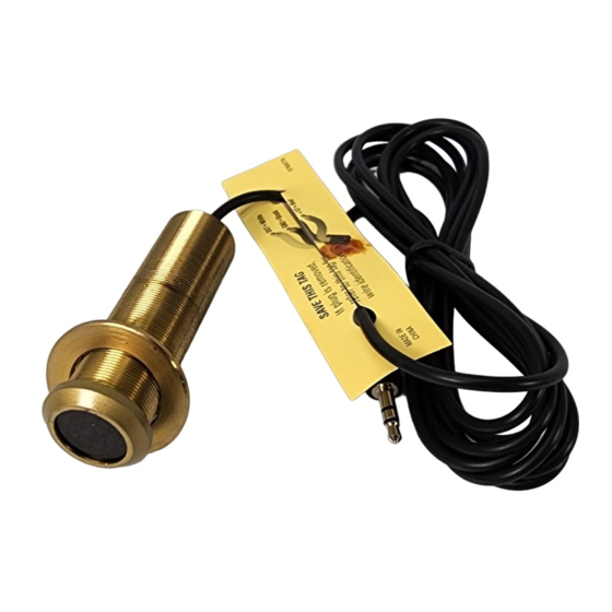
Micro Link™ Peep-Hole Style
CFL/LCD Proof IR Receiver
INSTALLATION INSTRUCTIONS
DESCRIPTION
The Micro Link IR Receiver is a small peep-hole style infrared repeater
assembly. The Micro Link IR Receiver is equipped with a 7-foot cable and a
3.5mm stereo mini plug, which is plugged directly into the "IR RCVR" jack on
the connecting block, such as the models 789-44, CB60, and 791-44. The
Micro Link IR Receiver is primarily intended for use in installations where the
connecting block is within reach of its 7-foot cable – as when installing the
Micro Link IR Receiver in a cabinet where the controlled equipment is behind
closed doors.
FEATURES & SPECIFICATIONS
•
Infrared carrier reception bandwidth: 30 – 60 kHz.
•
Ir Carrier Adjustment: 32 to 56 kHz (allows output carrier frequency to be
matched to a controlled component for optimum performance).
•
IR reception range: > 50 feet.
•
Dimensions: 2.75" Length x 0.75" DIA. Bezel is 0.90" DIA.
•
Works in normal 3-wire model (12VDC, IR, GND).
•
Red talkback LED for system verification.
•
RF grid included for EMI interference reduction.
•
Drives IR emitters through Xantech Connecting Blocks, Controllers, etc.
•
Power requirements: +12VDC, 20mA.
MODEL
INSTALLATION
QUICK-START
A typical system will use an IR receiver, several emitters, and a power supply
all connected to a connecting block.
1. Connect the IR receiver to the "IR RCVR" port on the connecting
block. The 'red' connector is installed to the 'red' plug.
Note: In some extended distances, additional 3-conductor may be required and can
be connected to the terminals on the connecting block.
2. Connect the Emitters to the connecting block. The 'yellow' connector
is installed to the 'yellow' plug.
3. Connect the power supply to the connecting block.
4. Installation complete
MOUNTING
Drill a 3/4" hole in any surface, such as a cabinet panel. Pass the lead and
the body of the 490 through the hole and secure from the rear with the nut
(supplied).
PLACEMENT
The IR receiver should be located so that it is not directly facing a light
source such as lamps or displays (standard, LCD, and Plasma). When
mounted near a display, it should be flush to the display and away from light
reflections that may occur.
LOCAL SYSTEM APPLICATION
In this system a 283D Blink-IR Designer Emitter is shown connected to the
"OUT" jack. If expansion beyond two emitters is required, use a Xantech 789-
44, CB60, or 791-44 Connecting Block.
Advertisement
Table of Contents

Related Manuals for Xantech Micro Link 49085D


Summary of Contents for Xantech Micro Link 49085D
- Page 1 In this system a 283D Blink-IR Designer Emitter is shown connected to the matched to a controlled component for optimum performance). “OUT” jack. If expansion beyond two emitters is required, use a Xantech 789- • IR reception range: > 50 feet.
- Page 2 CABLE CONNECTIONS IR CARRIER ADJUSTMENT 490’s may also be used where the 7-foot cable is not long enough. Simply The 49085D is factory set to an IR carrier repeat frequency of 38kHz. This cut off the mini plug, strip the leads and splice them to a 3-conductor will be correct for the majority of installations.
- Page 3 LARGE SYSTEM APPLICATION The 490D Series IR receiver is compatible with all Xantech Connecting [BLANK PAGE] Blocks. Different connecting blocks are provided for application specific situations. For instance, in the diagram below, a 791-44 connecting block is used to control several components.
- Page 4 Limited Warranty TROUBLE SHOOTING: Xantech® warrants its products to be free of defects in materials or workmanship. This is a 1. Perhaps the most common problem you may encounter is stray IR Limited Lifetime warranty from the date of purchase by the original consumer. Any products...
Need help?
Do you have a question about the Micro Link 49085D and is the answer not in the manual?
Questions and answers