Xantech MRC88 Installation Instructions Manual
Eight zone – eight source audio/video controller/amplifier system
Hide thumbs
Also See for MRC88:
- Installation instructions manual (102 pages) ,
- Quick start manual (44 pages) ,
- Feature descriptions (18 pages)

Subscribe to Our Youtube Channel
Related Manuals for Xantech MRC88


Summary of Contents for Xantech MRC88
- Page 1 INSTALLATION INSTRUCTIONS MODEL MRC88 EIGHT ZONE – EIGHT SOURCE AUDIO/VIDEO CONTROLLER/AMPLIFIER SYSTEM...
-
Page 2: Safety Instructions - Read Before Operating Equipment
18. Servicing – The user should not attempt to service the appliance beyond that described in the operating instructions. All other servicing should be referred to qualified service personnel. DO NOT REMOVE COVER (OR BACK) NO USER-SERVICEABLE PARTS INSIDE © 2003 Xantech Corporation Model MRC88... -
Page 3: Table Of Contents
IR Control Connections...26 Sense Input Connections ...26 ELATED IRING Speaker Connections...27 MRC88 Keypad CAT5 Cable Connections at the MRC88 Controller/Amplifier ...28 Video Connections...28 Status Connections and Common Control Out ...28 Preamp Out...29 CO1 and CO2 (Zones 7 & 8)...29 Zone IR ...29 AC Power Connections ...29... - Page 4 Using the RS232 Palette Editor ... 46 Testing RS232 Command Strings... 47 RS232 P REATING AN ALETTE SECTION 4: PROGRAMMING THE CONTROLLER ... 49 CONFIGURING SOURCE ICONS ON MRC88 KEYPAD LCD... 49 NTERING IRECTLY ONTO THE ICONS ... 50 REATING CONS...
- Page 5 ... 58 ODES OWER ANAGEMENT AND BASIC M ODE ARE AS FOLLOWS ... 61 ETTINGS ... 61 ... 65 ... 67 ... 68 ... 70 EQUENCES © 2003 Xantech Corporation ) ... 54 ... 59 ENSE RIGGERS :... 60 Page: 5...
- Page 6 FIRMWARE UPGRADE OPTIONIS... 79 OWNLOADING IRMWARE IRMWARE PGRADE IRMWARE PGRADE SECTION 7: TWEAKING THE SYSTEM... 80 TEACHING A HAND-HELD REMOTE TO OPERATE THE MRC88 SYSTEM... 80 EACHING A EACHING A MAKING FINE ADJUSTMENTS ... 81 RIMMING OURCE UDIO ... 82 DJUSTMENTS ...
- Page 7 Model MRC88 Page: 7 © 2003 Xantech Corporation...
-
Page 8: Section 1: General Information & Features
• One DB9 programming cable to connect to the RS232 serial port on your PC (Part No. 05913410) • One male DB15 to male DB15 cable with null modem for linking two MRC88 Controllers (Part No. 05913555) • CD-ROM Disc contains the MRC88 Dragon Drop-IR software (Part No. 03900785-01) •... - Page 9 Model MRC88 Page: 9 IMPORTANT NOTE: A MRC88 System can be a single controller with keypads for up to Eight zones or two connected controllers and keypads for up to Sixteen zones. There are three different setup modes in the Dragon Drop-IR Software.
-
Page 10: System Overview
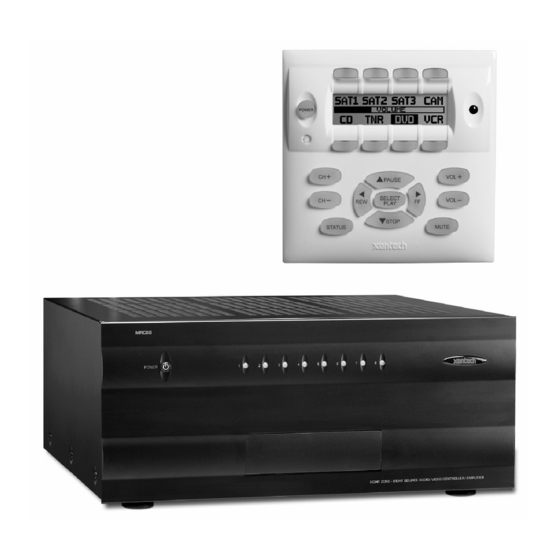
Model MRC88 SYSTEM OVERVIEW The MRC88 is a Eight-source Eight-zone audio/video distribution and control system. The System is comprised of a Control Amp, Eight LCD Keypads, and Eight 283M IR Emitters. Together the Control Amp and the Keypads make up a Whole-house Audio/Video Entertainment system. The Control Amp acts as the Server and the Keypads act as the Clients. -
Page 11: Controller/Amplifier Features
• IR Learning: IR commands can be learned from external hand-held remotes through the Controller/Amplifier’s built-in IR learning eye or they can be generated from the MRC88’s built-in IR code library. Internal IR Code Library: Built in IR Code Library. Contains all Major Brand Component IR commands. No need to ‘learn’... -
Page 12: Keypad Features
Flush-mount, snap-in wall unit with universal wall mounting plate. Requires a 4" x 4" hole cutout in wall (use included template). • Connects to MRC88 Controller/Amplifier via CAT5 cable terminated with RJ45 connectors. • Configurable LCD panel (via supplied Dragon Drop-IR™ software). -
Page 13: Mrc88 Controller/Amplifier Panel And Feature Descriptions
Model MRC88 MRC88 CONTROLLER/AMPLIFIER PANEL AND FEATURE DESCRIPTIONS Figure 2 – The Model MRC88 Controller/Amplifier – Front Panel Features and Functions MRC88 FRONT PANEL FEATURES AND CONNECTIONS: 1. Front Panel. 2. Chassis Feet. Set high enough to provide through-chassis cooling by natural convection. - Page 14 7. IR Learning Eye. The IR Eye on the MRC88 Controller front panel allows teaching IR Codes to Dragon Drop-IR™ via the Control Amp when connected to a PC ‘s com port.
-
Page 15: Mrc88 Rear Panel Features And Connections
Source Audio Inputs. Gold-plated RCA Jacks for Stereo/Dolby Pro line level audio input from source components. b) Source Video Inputs. Gold-plated RCA Jacks for composite video input from source components. c) Sense Inputs. 3.5mm Stereo Mini Phone Jacks for use with the CSM1 MRC88 Current Sense Module. © 2003 Xantech Corporation Page: 15... - Page 16 29. Com Port. DB9 RS232 Control Port allows full control from an external PC component of all Internal Amplifier Commands of the MRC88 Controller and the ability to trigger programmed IR Macros for control of devices connected to the Controllers emitter ports. The Com Port can also be used in the reverse to send ASCII/Hex commands OUT to control an external RS232 device directly from the MRC88 Keypad and/or handheld remote.
-
Page 17: Mrc88 Keypad Feature Descriptions
2. Power. Turns the zone ON and OFF. Can be programmed with IR codes or sequences. 3. IR Sensor. Receives IR from hand-held remotes to control both source components and the MRC88 system. A Programmable Learning Remote such as the Xantech URC2 is recommended for integrating the IR commands of the MRC88 and source components into a single controller. - Page 18 13. Status. Displays zone and system status. Allows access to Dynamic Zone Linking and Zone EQ/Balance settings (non-programmable). 14. Select/Play, Stop, Pause, Rew, FF. Each send IR commands programmed to these buttons to the selected source emitter, common emitter, and zone emitter outputs. © 2003 Xantech Corporation Model MRC88...
-
Page 19: Mrc88 Keypad - Rear Features And Connections
23. External IR Terminal Block. 4-Terminal WECO style socket – Allows connection of other Xantech IR Receivers and/or Keypads to be used in conjunction with the MRC88. (i.e. Use Waterpad Keypad in sub- zone in shower or outdoor zone or Plasma Friendly IR Receiver in place of Keypad IR Receiver). -
Page 20: Section 2: Installation & Connections
All 8 IR emitters to IR Emitter Ports 1 thru 8 (rear connection Item #26) g) AC Power for MRC88 Controller and Audio/Video Source Component 2. Press “Power On” button on the front of the MRC88 Controller/Amplifier (wait for front panel LED’s to stop flashing – should be less than 20 seconds). -
Page 21: Mrc88 Controller/Amplifier Physical Location And Mounting
MRC88 CONTROLLER/AMPLIFIER PHYSICAL LOCATION AND MOUNTING (BASIC/ADVANCED) When you mount the MRC88 Controller, you should plan its location carefully. Pay close attention to each of the following factors (refer to Figure 6A above): 1. The amplifier is convection cooled. That is, it depends on the natural free flow of air up through the slot perforations in the bottom plate, over the internal heat dissipating fins, then out the top cover, for adequate cooling. -
Page 22: Mrc88 Keypad Physical Location And Mounting
3. If the cabinet contains other heat generating components or you are using several MRC88's in a large multi- zone system, you will have to pay even closer attention to adequate ventilation. - Page 23 Any cut outside of the outline by more than ¼” may not be covered by the MRC88 Keypad. Figure 8 – Installing the MRC88 Keypad mounting bracket in the wall 2. Installing the Mounting Bracket a.
-
Page 24: Mrc88 Keypad Removal
Figure 10 as a guide for CAT5 termination. 4. Add or remove jumpers on the rear of the MRC88 keypad-according to Table 1 (Keypad connections). 5. Firmly snap the MRC88 Keypad into the bracket that you have just installed (see Figure 6). -
Page 25: Connecting The Mrc88 Controller/Amplifier
Figure 9 – Removing the MRC88 Keypad from the wall 1. Insert the MRC88 keypad removal tool into the slot at the bottom of the keypad, as shown in Figure 9, being sure that the tool is inserted so that the “insert to here” line slides under the Keypad. This will reduce the risk of damage to the Keypad or the wall. -
Page 26: Zone Audio Inputs
Plug the supplied 283M IR emitters into the appropriate IR Emitter jacks - Figure 3-(26). Be careful to match the source audio and video connection number on the MRC88 to the IR Emitter jack number. This will ensure that the IR control signal will be routed to the correct source component. Find the IR sensor window on the source component and attach the emitter to the components sensor window after removing the protective paper cover on the flat side of the emitter head. -
Page 27: Zone Related Wiring Connections
ZONE RELATED WIRING CONNECTIONS In typical applications, each zone will have at least one MRC88 Keypad and a pair of stereo speakers. In those zones with both audio and video, at least one video monitor or television will also be used. In order to make these connections, the minimum requirement is home runs of one CAT5 cable for each zone’s... -
Page 28: Mrc88 Keypad Cat5 Cable Connections At The Mrc88 Controller/Amplifier
ON and OFF with the zone ON/OFF condition. ON = +12VDC, OFF = 0VDC. Using a 3.5mm mono mini phone connector, this control can be used to close a relay, such as a Xantech CC12, to raise a TV lift or drop a projection screen automatically when a zone is turned ON. -
Page 29: Preamp Out
Using a 3.5mm mono mini phone connector, this control can be used to close relays (Xantech CC12) or turn on an AC outlet (Xantech AC1, AC2) for activity common to the system. Connect one end of the 3.5mm Mono Mini jack and the other end to the device to control. Tip=Control Voltage; Sleeve=GND... -
Page 30: Keypad Connections And Jumper Settings
2. Set Keypad Address jumper configuration on the rear of the keypad – Figure 5-(17) according to Table 1 below. 2. Connect the CAT5 cable from the MRC88 Controller/Amplifier into the RJ45 jack marked “Controller” on the rear of the MRC88 keypad. -
Page 31: Zone Expansion (Connecting Two Mrc88 Controllers)
The STATUS line is an output and is active Hi (+12VDC) when the MRC88 Keypad is powered ON and is LOW (0VDC) when the Keypad is OFF. Use this to provide Bank Tracking LED on the SMARTPAD/WATERPAD keypad or other. -
Page 32: Linking Two Mrc88 Controller/Amplifier Units
Figure 3-(23) to feed the source component inputs of the SECONDARY Unit – Figure 3-(22). All of the source components emitters should be connected to the PRIMARY Units IR Emitter Output Ports – Figure 3-(26). This rule applies to the SENSE INPUTS also. © 2003 Xantech Corporation... - Page 33 Page: 33 Extended Runs and Secondary Keypads In Zone Figure 11 – MRC88 Keypad CAT5 Cable Lengths The maximum cable length for CAT5 connections to a single keypad is 500 feet (see Figure 11-A). For two keypads in a zone, the distance to the last keypad is cut in half to 250 feet (see Figure 11-B). This same relationship applies to systems with 4 Keypads in the zone (Max distance to last keypad is 125ft.).
-
Page 34: Speaker Connections
If any keypad in the zone is using an external IR receiver, or if an outdoor keypad is necessary in a sub- zone, the MRC88 Terminal Block on the rear of the keypad (see Figure 12) can be used to expand the connections on the back of the keypad as shown in Figures 11A, B, &... -
Page 35: Setting-Up The Mrc88 System
Page: 35 SETTING-UP THE MRC88 SYSTEM (BASIC/ADVANCED) To better demonstrate the ease and versatility of programming the MRC88, Figure 13 will be used to illustrate setup for a typical application. (EXPANDED) For setup of an expanded system, see Figure 24. -
Page 36: Section 3: Pre-Programming The Mrc88
ADVANCED features are also programmed here including Zone Linking, Monitor Lockout, RS232 control, and IR Routing of received commands (to name a few). The actual keypads are not programmed in the system. All keypad functionality is contained in the MRC88 Controller/Amplifier. Each keypad access’s its functions via bi-directional communications between the keypad and the controller. -
Page 37: Planning The System
3. Perform the Out-of Box PRE TEST as outlined in Section 2. 4. Assemble the components into a working MRC88 system such as that shown in Figure 13. 5. Decide whether the MRC88 System will be programmed in BASIC, ADVANCED or EXPANDED modes BASIC MODE 6. -
Page 38: Included Hardware & Software Items
Install the DRAGMRC program onto your hard drive as follows: 1. Insert the disc into your computer’s CD-ROM drive. If your drive has been set for auto run, a Xantech Welcome Menu will appear. If not, access your CD ROM with Windows Explorer and double click the file "setup.exe". -
Page 39: Verifying Com Port Communication
(“Who Am I” Base Unit Version Verification) Before continuing, it is recommended to verify proper COM PORT communication between the PC and the MRC88. By checking the units Firmware versions and verifying a response from the MRC88, you will confirm proper communication and may continue. -
Page 40: Learning Ir Commands (Creating Palette Files)
Command Group is associated with your specific component. NOTE: To test commands out of the Library, the PC running DragMRC must be connected to the MRC88 via the RS232 or USB programming port. -
Page 41: Learning Ir Commands
Command Group listed (i.e. Cmd Group1). A list of all of commands associated with this component should be displayed. 2. Connect an Emitter to the COMMON emitter port on the rear of the MRC88 Controller/Amplifier – Figure 3-(27). -
Page 42: Recording Toggle Command Functions
If you continue to have problems learning commands, please see the Trouble Shooting section at the end of this manual. 9. Repeat steps 6 thru 8 for all of the source functions to be used on the MRC88 Keypad. Figure 17... -
Page 43: To Rename An Existing Function
OMMANDS IN THE ALETTE Be sure corresponding source for the commands to be tested is ON and connected to the MRC88 as described in the Out-Of-The-Box Pre Test section. 1. Connect an Emitter to the COMMON emitter port on the rear of the MRC88 Controller/Amplifier –... -
Page 44: Editing Brand, Component, And Function Lists
6. New Brands, Components and Functions can now be selected and programmed in Palette Editor. GETTING SOURCE COMMANDS FROM THE INTERNET ANTECH There are some IR commands that can be difficult to learn in Dragon. Xantech edits and posts some of these commands at http://www.xantech.com listings and download instructions.) A direct link to Xantech.com can be found in the “Links”... - Page 45 IMPORT to save. 12. A RED asterisk will now be displayed to the left of the function indicating the code has been successfully imported. 13. Repeat steps 8 thru 12 for all commands necessary. © 2003 Xantech Corporation Page: 45...
-
Page 46: Entering Rs232 Commands (Creating Rs232 Command Palette Files)
(i.e. Decimal, Hex, Binary, and ASCII). 9. Repeat steps 6 thru 8 for all of the source functions to be used on the MRC88 Keypad. Figure 20: Importing Discrete IR Codes ©... -
Page 47: Testing Rs232 Command Strings
There are two methods of testing RS232 Command Strings directly from the RS232 Palette Editor: One is directly out of the DragMRC PC’s Comport and the second method is through the MRC88’s RS232 Com Port – Figure 3-(29). Using both methods you can control the component or device directly for confirmation of command string or send the command to an RS232 Utility programming to verify proper output (this is good for Trouble Shooting purposes or for testing the program without the component or device present). -
Page 48: Creating An Rs232 Palette File
A Palette File is a file of learned commands that is ready to be placed onto the Virtual Keypads for use in the MRC88 system. These files can be shared with all future versions of Dragon Drop-IR™ Software for use with any Dragon programmable Xantech product capable of issuing RS232 commands. -
Page 49: Section 4: Programming The Controller
Section 4: Programming The Controller There are three ways in which the MRC88 can be controlled or to control your audio, video and home control systems; by pressing the buttons on the MRC88 Keypad, from signals received from an Infrared (IR) remote at the keypads IR Receiver eye, or from RS232 control from a touch screen panel or other RS232 controller device. -
Page 50: Entering Text Directly Onto The Icons
4. From the list, select the desired icon and click “OK” (or double-click the desired icon). The icon will appear in the ‘virtual LCD’ on the keypad in the MRC88 System Window. The source icon will appear in all zones on the ‘virtual’ keypads. -
Page 51: Placing Commands Onto The Virtual Keypad
SELECTING INTERNAL AMPLIFIER COMMANDS (ADVANCED/EXPANDED) To control the MRC88 Controller itself within a MACRO, use the MRC Amplifier Command Generator located under the PALETTE menu (or press F6 on the keyboard to access menu). These commands will directly control all functionality of the Controller without using the standard Keypad (i.e. Source Selection, Volume, Mute, etc. -
Page 52: Programming Sequences (Macros)
ROGRAMMING EQUENCES ACROS All programmable buttons on the MRC88 Keypad can be programmed to send IR sequences of up to 40 commands (all buttons except for Volume UP/DOWN and STATUS). 1. Click the button to be programmed. 2. Open all palettes to be used in the sequence. -
Page 53: Push & Hold (Tiered) Commands
These button edit functions can be accessed by right-clicking on the button. Doing so will display a pop-up menu of the different edit functions (see Figure 26 above). Each of the functions available are described below. Figure 26 Button Edit Pop-Up Menu © 2003 Xantech Corporation Page: 53... -
Page 54: Delete Key
Right-clicking on a command placed in the Macro Command List window will bring up a pop-up menu allowing an individual command to be deleted, routed to a specific Zone emitter output or to a Source emitter output (see Figure 27 above). Each of the functions available are described below. © 2003 Xantech Corporation Model MRC88... -
Page 55: Ir In Zone
(EXPANDED Zones 1 thru 16): Selecting any of these Zones in the list will route the highlighted IR command to the selected Zones IR emitter port on the rear of the MRC88 Controller as well as the In- Zone IR Emitter port on the rear of the Keypad (if enabled) regardless of which zones keypad issued the command. -
Page 56: Delete
The MRC88 Controller features two sensing methods. One is Video Sensing. All eight source video inputs are set to detect a video input signal (NTSC and PAL sync). When video is detected, the MRC88 controller knows when to send or not send power commands to keep components in sync with system activity. The other method is Current Sensing. - Page 57 4. Select POWER ON in the Macro Command List. The POWER ON button will become outlined in BLUE. 5. Select the appropriate POWER command to be associated with the MRC88 System ON condition NOTE: For components with discrete Power commands, select the POWER ON command.
-
Page 58: Programming Sense Trigger Codes
Sense input is False (i.e. commands placed under POWER OFF will be issued when the Sense Input signal is removed). It does not compare it to the Power State of the MRC88 Zone Power condition as it does in Power Management. -
Page 59: Polarity And Wiring Of Sense Input
2. Select the TEST button located in the bottom right-hand side of the Power Management window. Commands listed under the Macro Command List for that selected sense trigger should now be executed in order of appearance out of the proper Emitter Ports on the MRC88 Controller. © 2003 Xantech Corporation... -
Page 60: Zone Options Configuration
RC68 CODE GROUP The RC68+ Code Group refers to the group of IR codes that will be used to control the MRC88 System. The number associated with this Code Group refers to the dial setting on the rear of the RC68+ handheld programmer. -
Page 61: Pre Amp Volume Adjust Settings
“SYSTEM CODE GROUP” box and select one of the displayed Code Group choices. (ADVANCED/EXPANDED) Each zone of the MRC88 can be set to it’s own individual Code Group. This may be useful when the system requirements so dictate. (i.e. The system requirement calls for having zone-specific remote controls). Since... -
Page 62: Transferring The Project
TRANSFERRING THE PROJECT (BASIC) The project can now be transferred to the MRC88 if it is being set up in the Basic mode. For Advanced and Expanded systems, continue to next section. See page 77 “Transferring a Project” for instructions. -
Page 63: Model Mrc88 Page
(Factory Default = “DISABLED”) Select ENABLE to utilize the Zone Audio Inputs on the rear of the MRC88 Controller Amplifier - Figure 3-(24). Use this feature to interface Zone Specific audio components such as a Multi Zone Audio Server or individual zone CD, MP3 Hard Disk Player or other zone specific audio source. -
Page 64: Ir Routing
EXPANDED OPTIONS (Factory Default = “Not Expanded”) XPANDED This mode is for systems operating with ONE MRC88 Controller/Amplifier (8 Zones or less). This is the DEFAULT mode of operation. XPANDED This mode is for systems operating with TWO MRC88 Controller/Amplifiers connected via the units Expansion ports. -
Page 65: Rs232 Settings
(Factory Default = “ENABLED”) This setting should be enabled when the RS232 port will be used to receive data to control the MRC88 System from a PC or other RS232 device. If the RS232 port will only be used to control an external device from the Keypad (thermostat controller, lighting system etc..), disable this setting to prevent the MRC88 system from... -
Page 66: Dynamic Monitor Lockout (Administrator)
2. Click the “ADMINISTRATOR” box for any zone that is to have ‘Dynamic Monitor Lockout’ ability. 3. After the project has been transferred to the MRC88 Controller, on a keypad in a zone with ‘Administrator’ control, simultaneously press the ”STATUS” and “SOURCE” buttons for the device to be ‘locked out’. -
Page 67: Zone Linking Programming
ZONE LINKING PROGRAMMING Zones in the MRC88 System can be linked together to allow any combination of zones to behave as a single zone with regard to power (ON/OFF) and source selection. If Zones 1 and 2 are linked, when either is turned ON or OFF, both will turn ON or OFF simultaneously. -
Page 68: Dynamic Zone Link Mode
Page: 68 NOTE: After the project has been transferred to the MRC88 Controller, the Zones will be permanently linked unless reprogrammed to be otherwise. All linked zones will have a small ‘L’ in the right side of the Volume Bar located in the LCD display on the keypad(s) in those zones. Simultaneously pressing the “STATUS”... -
Page 69: Link All Dynamic
Macro to control any number of IR controlled devices. This can give the ability for a central PC (or other RS232 device) to control not only the MRC88 system itself, but also any IR controlled device connected to any of the MRC88 emitter ports. -
Page 70: Programming Ir Commands And Sequences
Commands placed under ASCII Commands in the RS232 Input Translator window may be tested prior to downloading to the MRC88 Controller. To test commands, the Dragon PC must be connected to the front panel COM PORT or USB Port and emitters must be placed in the proper Source and Zone IR Emitter output ports. -
Page 71: Rc68+ Ir Code Triggered Sequencer
The MRC88 Controller/Amplifier can generate IR code sequences triggered by single RC68+ commands. This feature can be useful in eliminating long sequence execution from hand-held controllers and also allow a wider range of programmable remotes that can be used with MRC88 (i.e. Remotes that do not allow sequence programming). -
Page 72: Editing Individual Commands
Zone, this sequence will be initiated. By teaching the ‘80’ command to a hand held remote, it is now only necessary to send the one IR code and have the sequence generated by the MRC88. PROGRAMMING INTERNAL AMPLIFIER COMMANDS To access the MRC88 Internal Command Generator, click on the Palette Menu in the MRC88 System Window, and select “MRC AMPLIFIER COMMAND GENERATOR”... - Page 73 ON. Though RC68+ commands can be used to control the MRC88 via remote control, RC68+ commands will not be recognized by the MRC88 Controller’s microprocessor if generated by a MRC88 Keypad.
-
Page 74: Zone Expansion (Connecting Multiple Mrc88 Controllers)
ZONE EXPANSION (CONNECTING MULTIPLE MRC88 CONTROLLERS) Two MRC88 Controllers can be used to expand the number of zones in a MRC88 system to SIXTEEN. The two MRC88 System Controllers interface via their Expansion port located on the rear of each Controller [Figure 3- (30)]. -
Page 75: Programming In Expanded Mode
NOTE: During the EXPANDED Set-Up instructions, we will refer to the PRIMARY and SECONDARY Controllers. The PRIMARY Controller refers to the MRC88 Controller connected to Zones 1 thru 8 and the SECONDARY Controller refers to the MRC88 Controller connect to Zones 9 thru 16. - Page 76 RS232 Connector ONLY regardless of which zone is issuing the command. This means if interfacing to another RS232 device, this device will need to be connected to the PRIMARY Controllers RS232 port. Figure 42: Expanded Controller Connections © 2003 Xantech Corporation...
-
Page 77: Transferring A Project To The Mrc88
Proceed as follows: 1. Be sure the MRC88 Controller and the PC are connected via the COM port or USB port on the front of the MRC88, that power is applied to the MRC88, the MRC88 is connected to all sources and Keypads, and the MRC88 is operating properly (see Out-of-the-Box in previous chapters). -
Page 78: Saving And Backing-Up Files
3. If there are no changes to the system (type of sources, brand of sources, zone configuration etc.) transfer the project. If there are any changes to be made, modify the new project and then transfer to the MRC88 Controller. ACKING... -
Page 79: Firmware Upgrade Optionis
1. Open the Dragon Drop-IR™ MRC88 software. Make sure you have an Internet connection as well as having the MRC88 connected to your computer’s COM port (or USB port). 2. With the MRC88 powered ON, press the LEVEL RESET button on the front of the unit [Figure 3-(6)] two times within a second. -
Page 80: Section 7: Tweaking The System
4. Connect a 282M Emitter on the COMMON Emitter output [Figure 3-(27)] of the MRC88 Controller 5. Make sure the PC is connected to the front panel COM Port (or USB port) and the MRC88 is powered ON. (Do a BASE UNIT “WHO AM I” to confirm communication between the PC and MRC88). -
Page 81: Making Fine Adjustments
1. Using an RC68+ with overlay “A”, select the input that has the lowest apparent volume level (from any zone). 2. Point the RC68+ at the IR sensor on the MRC88 Keypad (IR sensor enabled) and press the TRIM button (button F8). This activates the TRIM mode. -
Page 82: Zone Adjustments
1. Go to desired zone. 2. Using an RC68+ select desired INPUT (source). 3. Point the RC68+ at the IR sensor on the MRC88 Keypad (IR sensor enabled) and press the Z-ADJ button (18). (This activates the Zone Adjustments mode). -
Page 83: Section 8: Operating Instructions
Model MRC88 Section 8: Operating Instructions With all system components connected and the MRC88 Controller and Keypads programmed, The system is ready for use. The following instructions are for the end-user on how to operate the system on a daily basis. -
Page 84: Zone Settings
LCD in the linked zones. The zones will be linked for power and source selection only. Volume, Mute and individual IR buttons will not be linked. To Unlink Zones: Simultaneously press “STATUS and the “CH+” button. The ‘Link Session’ message will appear. © 2003 Xantech Corporation Model MRC88... - Page 85 (LED /green, LCD/normal display). The small ‘L’ will no longer appear. The zones will resume independent control. (EXPANDED) Same as above, using the Status button in “Link Session” to access zones 9-16. © 2003 Xantech Corporation Page: 85...
-
Page 86: Section 9: Appendix
ASCII STRING ‘INITIATING’ AND ‘TERMINATING’ CHARACTERS The protocol was designed to be similar to the one used in the Xantech ZPR68 so that it would be familiar. It is different from the ZPR68 in that the MRC88 has a buffered UART and is therefore able to receive a complete command/query string at one time. - Page 87 This setting can be found with the settings for configuring the COM port. For the MRC88 system to recognize incoming ASCII command strings, the string must begin with an ‘!’ and for data queries the string must begin with a ‘?’. All strings must end with a ‘+’. This way it can determine the beginning and end of the string for processing.
- Page 88 Execute Keypad Button !{z#}MK{k#}X{i#}+ COMMANDS EXAMPLES/COMMENTS To turn on Zone 2: !2PR1+ To turn off Zone1: !1PR0+ To set Zone 1 to Source Input 5: !1SS5+ To mute Zone 3: !3MU1+ To unmute Zone 4: !4MU0+ © 2003 Xantech Corporation Model MRC88...
- Page 89 Zone 1 currently has a treble ?1TR7+ value of 7 (flat) Zone 1 currently has a bass ?1BS7+ value of 7 (flat) Zone 2 currently has a ?2BA31+ balance value of 31 (even) © 2003 Xantech Corporation Page: 89 EXPLANATION...
- Page 90 -6.25 -7.50 -8.75 -10.00 -11.25 -12.50 -13.75 -15.00 -16.25 -17.50 -18.75 -20.00 -21.25 -22.50 -23.75 -25.00 -27.50 -30.00 -32.50 -35.00 -37.50 -40.00 -42.50 -45.00 -47.50 -50.00 -52.50 -56.25 -60.00 -63.75 -67.50 -71.25 -75.00 -78.75 © 2003 Xantech Corporation Model MRC88...
- Page 91 Tier 2 Source Select 8 Tier 2 CH + Tier 2 CH - Tier 2 POWER NOT AVAILABLE Tier 2 MUTE Tier 2 PAUSE Tier 2 STOP Tier 2 FF Tier 2 REW Tier 2 SELECT/PLAY © 2003 Xantech Corporation Page: 91...
- Page 92 Page: 92 BASS/TREBLE LEVEL MRC88 SETTING LEVEL (in dB) © 2003 Xantech Corporation Model MRC88...
- Page 93 Model MRC88 BALANCE LEVEL MRC88 Setting (63 steps) Left Speaker Attenuation (in dB) … … -1.25 -2.5 … … -37.5 Mute © 2003 Xantech Corporation Right Speaker Attenuation (in Mute -37.5 -36.25 … -2.5 -1.25 … Page: 93...
-
Page 94: Troubleshooting
If you encounter problems, review each of the following items and take corrective action as described. If problems persist, contact Xantech Technical Support. PROBLEM The MRC88, after a successful Transfer from Dragon Drop-IR, will not send out any IR commands. A corrupted or incorrectly learned IR code has been transferred to the keypad. - Page 95 You may have to experiment with the distance the remote is held away from the IR SENSOR on the back of the MRC88. For most cases it will need to be within one inch of the Learning eye. b) Vary the amount of time you hold down the "teaching"...
- Page 96 "Transfer aborted-Receiver Stopped Responding" or a "Communications Error---" message. After transferring commands to the MRC88, it works fine ... except at certain times the MRC88 refuses to output any commands at all. The STATUS LED under the POWER button on the Keypad is never illuminated GREEN or flickers constantly.
-
Page 97: Rs232 And Expansion Pin Out Information
Model MRC88 PROBLEM Problems Controlling the MRC88 via the RS232 port on the rear of the system. Problems controlling an External Device via the MRC88 rear Com Port RS232 AND EXPANSION PIN OUT INFORMATION PROBABLE CAUSE AND SOLUTION 1. Check the cabling between the controlling unit 2. - Page 98 IR Source 2 IR Source 3 HS Out IR Source 4 IR Source 5 HS In IR Source 6 IR Source 7 IR Source 8 IR Common Tx Out Common Rx In Sig Out Sig In © 2003 Xantech Corporation Model MRC88...
-
Page 99: Specifications
Weight (Keypad): ... 0.6 lbs (0.3 kg) CERTIFICATIONS Product is certified as marked on the rear panel. TMRA 30° Celsius - If this temperature is exceeded, you will need to provide additional ventilation to insure proper operation. © 2003 Xantech Corporation Page: 99... - Page 100 Page: 100 Model MRC88 © 2003 Xantech Corporation...
- Page 101 Model MRC88 Page: 101 © 2003 Xantech Corporation...
- Page 102 Page: 102 Model MRC88 XANTECH CORPORATION 12950 Bradley Avenue, Sylmar CA 91342-3829 phone 818.362.0353 • fax 818.362.9506 www.xantech.com Part No. 08901180 Rev B 06-02-03 © 2003 Xantech Corporation...
Need help?
Do you have a question about the MRC88 and is the answer not in the manual?
Questions and answers