
Related Manuals for Xantech MRC44


Summary of Contents for Xantech MRC44
- Page 1 INSTALLATION INSTRUCTIONS MODEL MRC44 FOUR ZONE – FOUR SOURCE AUDIO/VIDEO CONTROLLER/AMPLIFIER SYSTEM...
- Page 2 18. Servicing – The user should not attempt to service the appliance beyond that described in the operating instructions. All other servicing should be referred to qualified service personnel. DO NOT REMOVE COVER (OR BACK) NO USER-SERVICEABLE PARTS INSIDE © 2002 Xantech Corporation Model MRC44...
-
Page 3: Table Of Contents
Connecting the MRC44 Controller/Amplifier ...16 Connections at the Zone Location ...19 Setting-Up the MRC44 System ...21 Planning the System...23 Programming the MRC44 System Using the DRAG450MRC Software Software Setup ...23 Learning the IR Commands...24 Editing and Testing IR Commands ...25 Putting Codes to Work in the MRC44 ...26... -
Page 4: General Information
URC2P or URC2B IMPORTANT NOTE: A MRC44 System can be a single controller with keypads for up to four zones or two connected controllers and keypads for up to eight zones. There are three different setup modes in the Dragon Drop-IR Software. -
Page 5: System Overview
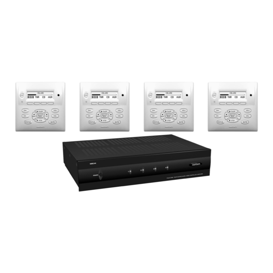
Model MRC44 SYSTEM OVERVIEW The MRC44 is a four-source four-zone audio/video distribution and control system. The System is comprised of a Control Amp, four LCD Keypads, and four 283M IR Emitters. Together the Control Amp and the Keypads make up a multi-room A/V system. The Control Amp acts as the Server and the Keypads act as the Clients. -
Page 6: Controller/Amplifier Features
Also available in 230 VAC / 50 Hz. Zone Features/Specifications • Each zone has 1 RJ45 connector for MRC44 keypad, 1 composite video output, 1 speaker-pair terminal and a 12VDC status output. • Multiple zones can be linked to behave as one zone. -
Page 7: Mrc44 Controller/Amplifier Panel And Feature Descriptions
Model MRC44 MRC44 CONTROLLER/AMPLIFIER PANEL AND FEATURE DESCRIPTIONS Figure 2 – The Model MRC44 Controller/Amplifier – Front Panel Features and Functions 1. Front Panel. 2. Chassis Feet. Set high enough to provide through-chassis cooling by natural convection. 3. Master AC Line On/Off Switch. Turns AC power On/Off to the entire unit. - Page 8 Source Audio Inputs. Gold-plated RCA Jacks for line level audio input from source components. b) Source Video Inputs. Gold-plated RCA Jacks for composite video input from source components. c) Sense Inputs. 3.5mm Stereo Mini Phone Jacks for use with the CSM1 MRC44 Current Sense Module. © 2002 Xantech Corporation...
- Page 9 Dragon Drop-IR Software from a PC. Also used for linking multiple MRC44 Controllers in Expanded Configurations. 15. IR Learning Eye. The IR Eye on the MRC44 Controller back panel allows teaching IR Codes to Dragon Drop-IR via the Control Amp when connected to a PC from the com port.
-
Page 10: Mrc44 Keypad Feature Descriptions
21. Power. Turns the zone ON and OFF. Can be programmed with IR codes or sequences. 22. IR Sensor. Receives IR from hand-held remotes to control both source components and the MRC44 system. A Programmable Learning Remote such as the Xantech URC2 is recommended for integrating the IR commands of the MRC44 and source components into a single controller. - Page 11 35. Select/Play, Stop, Pause, Rew, FF. Each send IR commands programmed to these buttons to the selected source and common emitter outputs. Figure 5 – The Model MRC44 Keypad – Rear Panel Features and Functions © 2002 Xantech Corporation Page: 11...
-
Page 12: Operation - Out-Of-The-Box
Sources IR emitters 2. Press “Power On” button on the front of the MRC44 Controller/Amplifier (wait for front panel LEDs to stop flashing – should be less than 20 seconds). 3. Turn on the Zone 1 TV/monitor and select the appropriate input (on the TV or monitor). -
Page 13: Installation
Be sure to allow enough room for the leads and dress them in such a manner so as not to block airflow. 7. The MRC44 is designed for mounting on flat horizontal surfaces. When mounting into a 19" rack, use a rack shelf or drawer. - Page 14 NOTE: Check local electrical codes. Some areas require a backbox in certain applications. For installations that require a backbox, see Xantech Part# MRCBOX. The MRC44 keypad will not fit in a standard 2-gang box. The Xantech MRCBOX must be used in applications that require a backbox.
-
Page 15: Mrc44 Keypad Removal
Figure 9 – Removing the MRC44 Keypad from the wall 1. Insert the MRC44 keypad removal tool into the slot at the bottom of the keypad, as shown in Figure 9, being sure that the tool is inserted so that the “insert to here” line slides under the Keypad. This will reduce the risk of damage to the Keypad or the wall. -
Page 16: Connecting The Mrc44 Controller/Amplifier
Plug the supplied 283M IR emitters into the appropriate IR out jacks. Be careful to match the source audio and video connection number on the MRC44 to the IR emitter jack number. This will ensure that the IR control signal will be routed to the correct source component. Find the IR sensor window on the source component and attach the emitter to the sensor window after removing the protective paper cover on the flat side of the emitter head. - Page 17 (or any combination of speakers) is 4-Ohms minimum. 3. Be sure to observe correct polarity by connecting the "+" and "–" terminal from each channel on the MRC44 to the corresponding "+" and "–" terminals on each speaker. This will ensure correct "phasing". Since the connectors are removable, you may unplug them for ease of lead assembly.
- Page 18 ON/OFF condition. ON = +12VDC, OFF = 0VDC. Using a 3.5mm mono mini phone connector, this control can be used to close a relay, such as a Xantech CC12, to raise a TV lift or drop a projection screen automatically when a zone is turned ON.
-
Page 19: Connections At The Zone Location
2. Connect the CAT5 cable from the MRC44 Controller/Amplifier into the RJ45 jack marked “Controller” on the rear of the MRC44 keypad. 3. Depending on the number of MRC44 keypads and IR receivers used in a zone the jumper pins on the MRC44 keypad are to be connected as shown in the following table:... - Page 20 Figure 12 – MRCCB1 MRC44 Connecting Block If both keypads in the zone are using an external IR receiver, the MRC44 Connecting Block (see Figure 12) is used to expand the connections on the back of the primary keypad as shown in Figure 11-C.
-
Page 21: Setting-Up The Mrc44 System
RF output on the Modulator to the RF/ANT in on the zone TV. SETTING-UP THE MRC44 SYSTEM (BASIC/ADVANCED) To better demonstrate the ease and versatility of programming the MRC44, Figure 13 will be used to illustrate setup for a typical application. (EXPANDED) For setup of an expanded system, see Figure 24. - Page 22 Page: 22 Model MRC44 Figure 13 –Typical MRC44 System © 2002 Xantech Corporation...
-
Page 23: Planning The System
Xantech. (Also check with local Authorized Xantech Distributor). Connections Connect the DB9 connector to your PC serial port and to the COM PORT on the rear panel of the MRC44. Software Installation Install the DRAG450MRC program onto your hard drive as follows: 1. -
Page 24: Learning The Ir Commands
6. Select the command from the left side of the Palette Editor (i.e. Power, Play, Stop etc.). 7. Hold the source remote up to the IR learning eye (Figure 3, #15) on the rear of the MRC44 Controller/Amplifier. -
Page 25: Editing And Testing Ir Commands
Check the "Toggle" box only if commands do not seem to execute consecutively or consistently. CAUTION: The older MRC44 firmware v218 or older) will output commands recorded with the toggle function but they will not execute the toggle action. For the majority of controlled products this will not be a problem. -
Page 26: Putting Codes To Work In The Mrc44
When finished, click the Close button. Any changes will be saved automatically. PUTTING CODES TO WORK IN THE MRC44 There are two ways in which the MRC44 can control your audio, video and home control systems; by pressing the buttons on the MRC44 Keypad or from an Infrared (IR) remote control. -
Page 27: Model Mrc44 Page
“BASE UNIT” Pull Down in the Menu bar and select “MRC44”. The MRC44 “ADVANCED SYSTEM WINDOW” will appear. Select the Controller tab. In the Expanded Options box, select ‘EXPANDED’. A message…”Please wait” will appear for about 10 seconds. A "virtual keypad", default source buttons (SRC1, SRC2 etc.) buttons which allow selection of Zone (1-8), along with tabs Sense... - Page 28 4. From the list, select the desired icon and click “OK” (or double-click the desired icon). The icon will appear in the ‘virtual LCD’ on the keypad in the MRC44 System Window. The source icon will appear in all zones on the ‘virtual’...
- Page 29 Model MRC44 Creating New Icons 1. Click on the “ICON EDITOR” tab in the MRC44 System Window. The ‘Icon Editor’ window will appear. 2. Click “NEW”. This will clear the screen. 3. To type a new source name, using the PC keyboard, Select “TEXT”. A source name, or icon, up to four characters in length can be created.
- Page 30 Getting Source Commands From The Internet Xantech.com There are some IR commands that can be difficult to learn in Dragon. Xantech edits and posts some of these commands at xantech.com under Products/IR Code Libraries. (See website for listings and download instructions.) A direct link to xantech.com can be found in the “Links”...
-
Page 31: System Set-Up Procedures
In basic mode, the code group can only be set for the entire system. (ADVANCED/EXPANDED) Each zone of the MRC44 can be set to it’s own individual Code Group. This may be useful when the system requirements so dictate. (i.e. The system requirement calls for having zone-specific remote controls). The Code Group Number assigned and preset at the factory for each zone of the MRC44 is 48. -
Page 32: Programming The Mrc44 Controller/Amplifier
(BASIC/ADVANCED/EXPANDED) With the ability to turn the system ON and OFF from more than one location, The MRC44 Controller needs to know when the different sources are ON or OFF and be able to know when to send or not send power commands to keep the sources in sync with the system. -
Page 33: Programming Power Management And Sense Trigger Codes
When a DVD player or TV is turned ON, have the video signal trigger an IR code to be issued via the common IR output to a Xantech IRS232 that could then send ASCII commands to a lighting system to set room lighting. -
Page 34: Advanced/Expanded Programming
Transferring The Project (BASIC) The project can now be transferred to the MRC44 if it is being set up in the Basic mode. For Advanced and Expanded systems, continue to next section. See page 41 “Transferring a Project” for instructions. - Page 35 2. Click the “ADMINISTRATOR” box for any zone that is to have ‘Dynamic Monitor Lockout’ ability. 3. After the project has been transferred to the MRC44 Controller, on a keypad in a zone with ‘Administrator’ control, simultaneously press the ”STATUS” and “SOURCE” buttons for the device to be ‘locked out’. If any zone has that same source selected, the audio will mute and the video will go blank.
-
Page 36: Zone Linking
Zone1/Zone 2 box and the Zone 2/Zone 1 box to show that these two zones are now tied together. 2. After the project has been transferred to the MRC44 Controller, all linked zones will have a small ‘L’ in the upper right corner of the LCD on the keypad(s) in those zones. - Page 37 1. Open the Dragon Drop-IR™ MRC44 software. Make sure you have an Internet connection as well as having the MRC44 connected to your computer’s COM port. 2. With the MRC44 powered ON, press the LEVEL RESET button on the back of the unit two times within a second.
-
Page 38: Rc68+ Ir Code Triggered Sequencer
Any Internal Amplifier Commands will be processed by the MRC44 Controller/Amplifier internally. In the MRC44 System Window, Click on RC68 in the lower right hand corner of the MRC44 System Window and the image shown in Figure 22 will appear. -
Page 39: Programming Internal Amplifier Commands
“DELAY” to the desired length. Left click and drag the delay box, into the command list between “INPUT” and “PLAY”. It will appear on the command list. 8. The sequence can be tested with the PC connected to the MRC44 com port by selecting the RC68 command and clicking on “TEST”. - Page 40 5. Two Parameter boxes will appear as shown in Figure 23, to set the action of the command. (e.g. Zone 1 and Source 1). 6. A table of MRC44 Controller/Amplifier commands is shown in Table 2 below with the associated controls. 7. Click “ACCEPT” when the Internal Amplifier Command is set to the desired state.
-
Page 41: Transferring A Project To The Mrc44
Proceed as follows: 1. Be sure the MRC44 Controller and the PC are connected via the COM port on the back of the MRC44, that power is applied to the MRC44, the MRC44 is connected to all sources and Keypads, and the MRC44 is operating properly (see Out-of-the-Box in previous chapters). -
Page 42: Fine Tuning
1. Using an RC68+ with overlay “A”, select the input that has the lowest apparent volume level (from any zone). 2. Point the RC68+ at the IR sensor on the MRC44 Keypad (IR sensor enabled) and press the TRIM button (F8). (This activates the TRIM mode). - Page 43 1. Go to desired zone. 2. Using an RC68+ select desired INPUT (source). 3. Point the RC68+ at the IR sensor on the MRC44 Keypad (IR sensor enabled) and press the Z-ADJ button (18). (This activates the Zone Adjustments mode).
-
Page 44: Operating Instructions
Zone Control (BASIC/ADVANCED/EXPANDED) 1. Press the ”POWER” button on any keypad. The MRC44 Controller will turn ON. If Power Management has been enabled, source components will turn on also. 2. Select a Source. Operate the source with the appropriate commands (CD PLAY, TUNER UP etc) 3. - Page 45 (rapid amber flash) for 10 seconds after the last button press, then ‘time out’ and return to normal use mode (LED /green, LCD/normal display). The small ‘L’ will no longer appear. The zones will resume independent control. (EXPANDED) Same as above, using the Status button in “Link Session” to access zones 5-8. © 2002 Xantech Corporation Page: 45...
-
Page 46: Zone Expansion Using Multiple Mrc44 Controllers
Each of the source components, DVD, SAT, VCR, CD have their A/V outputs running through an AV61 to the A/V inputs on the two MRC44 Controllers. In this configuration, any one of the eight zones in the system can select and monitor any of the four sources program material. - Page 47 Model MRC44 Page: 47 Figure 24 – Expanded System Diagram © 2002 Xantech Corporation...
-
Page 48: Troubleshooting
If you encounter problems, review each of the following items and take corrective action as described. If problems persist, contact Xantech Technical Support. PROBLEM The MRC44, after a successful Transfer from Dragon Drop-IR, will not send out any IR commands. A corrupted or incorrectly learned IR code has been transferred to the keypad. - Page 49 "Waiting for IR from your Remote" display times out with the "No IR Recorded" dialog box. Your computer is not recognizing or finding the serial port connection to the MRC44. PROBABLE CAUSE AND SOLUTION Try the following in the order listed:...
- Page 50 You may have to experiment with the distance the remote is held away from the IR SENSOR on the back of the MRC44. It may need to be as much as 10" away, but usually not closer than 1/2". b) Vary the amount of time you hold down the "teaching"...
- Page 51 "Transfer aborted-Receiver Stopped Responding" or a "Communications Error---" message. After transferring commands to the MRC44, it works fine ... except at certain times the MRC44 refuses to output any commands at all. Windows and Microsoft are registered trademarks of Microsoft Corporation.
-
Page 52: Specifications
TMRA 30° Celsius - If this temperature is exceeded, you will need to provide additional ventilation to insure proper operation. XANTECH CORPORATION phone 818.362.0353 • fax 818.362.9506 www.xantech.com Part No. 08901160 Rev B 06-28-2002 © 2002 Xantech Corporation Model MRC44...
Need help?
Do you have a question about the MRC44 and is the answer not in the manual?
Questions and answers