Xantech MRC88 Quick Start Manual
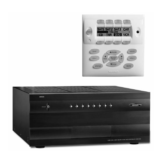
Eight zone - eight source audio & video controller/amplifier systems
Hide thumbs
Also See for MRC88:
- Installation instructions manual (102 pages) ,
- Feature descriptions (18 pages) ,
- Installation instructions (2 pages)

Related Manuals for Xantech MRC88


Summary of Contents for Xantech MRC88
- Page 1 QUICK START GUIDE MRC88 MRAUDIO8X8 EIGHT ZONE – EIGHT SOURCE AUDIO & VIDEO CONTROLLER/AMPLIFIER SYSTEMS Get other manuals https://www.bkmanuals.com...
-
Page 2: Table Of Contents
Head End Connections............................16 Zone Connections..............................16 SYSTEM INITIALIZATION ...............................17 OUT-OF-BOX SYSTEM FUNCTIONALITY .........................17 SYSTEM DEFAULT SETTINGS ..........................18 ZONE AUDIO ADJUSTMENTS (MRC88 Keypad – User Settings) ................19 AUDIO ADJUSTMENTS (Z-Adjust – Installer Settings) ...................19 Trim ..................................19 Zone Audio Adjustments ............................20 RESTORE SYSTEM DEFAULT SETTINGS........................21 PROGRAMMING –... -
Page 3: Read This First
This Guide only provides instruction to the most basic application of a MRC88 System as used in a multi-zone audio/video system using standard MRC88 Keypads. Advanced options such as integrating Xantech SPLCD Touchpanels... - Page 4 MRC88 / MRAUDIO8X8 QUICK START GUIDE Figure 1 – Typical MRC88 System 08905142A Get other manuals https://www.bkmanuals.com...
-
Page 5: System Planning
2. Provide large holes in the shelf below the MRC88 and allow at least 2 inches of space above the top cover to allow adequate airflow. -
Page 6: Mounting The Keypad
To mount the Keypad, use a plastic, dual-gang, new construction or retro fit J- box and the included MRC88 Keypad Mounting Bracket as shown in Figure 3. NOTE: Do not mount the Keypad in the same box with high voltage (AC) devices. -
Page 7: Keypad Cable Length
MRC88 / MRAUDIO8X8 QUICK START GUIDE KEYPAD CABLE LENGTH The maximum cable length for MRC88 connection to a single keypad is 500 feet (152m) over CAT5 cable. • Zone Keypad CAT5 cables should be pulled in home-runs from the keypad locations to the MRC88 Controller. -
Page 8: Speaker Wire Length
• Label each end of the speaker wire with the Zone Number and Room Name to assure proper connection and assist in troubleshooting. • MRC88 Speaker Terminals are 4-Ohm safe. Be sure the combined impedance presented to the speaker terminals by the speakers (or any combination of speakers) is greater than 4-Ohms. -
Page 9: Video Monitor Cable Length (Mrc88)
MRC88. • Coax must be properly terminated with a shielded male RCA video plug on the MRC88 end and as appropriate for connection to the video display. (Shielded male RCA plug typical) • Label each end of the coax with the Zone Number and Room Name to assure proper connection and assist in troubleshooting. -
Page 10: Preparation - Wiring
CAUTION: Power voltage for the keypad is transmitted along the CAT5 cable! Incorrect wiring on this cable can destroy the MRC Keypad! TERMINATING THE CAT5 CABLES All MRC88 CAT5/RJ45 connections utilize the EIA/TIA 568B Standard pin-out as shown in Figure 7. Figure 7 – CAT5/RJ45 Pin-out (EIA/TIA 568B) Cables should be configured in a pass through (pin to pin) configuration. -
Page 11: Ac Power
6 and the negative probe is on pin 3. See Figure 7. AC POWER It is recommended, but not required, that the MRC88 Controller and head-end source components be powered by a dedicated 20-amp circuit with an isolated ground. -
Page 12: Source Connections
MRC88 / MRAUDIO8X8 QUICK START GUIDE SOURCE CONNECTIONS Be sure the MRC88 power is off and the unit is disconnected the from the AC supply when making connections to avoid potential electrical shock and damage to the MRC88, the Keypads, Sources and Speaker components. -
Page 13: Ir Emitters
3. Carefully pull the emitter wire around to the back of the unit. Do not block disc and tape accesses. Do not pinch the wire between components. 4. Plug the emitter into the appropriate source IR Emitter Output on the MRC88 rear panel. -
Page 14: Connections
Head End Connections 1. Connect the zone CAT5 keypad cable to the appropriate Zone Keypad Terminal on the MRC88 rear panel. Be sure the RJ45 connector ‘clicks’ into place. 2. Repeat for all zones. -
Page 15: Speakers
MRC88 / MRAUDIO8X8 QUICK START GUIDE SPEAKERS Head End Connections Use the included 4-conductor plug-in connectors, (6 included) to connect speaker wires to the MRC88. 1. Strip each speaker wire conductor’s insulation back about ¼ inch (6mm) and twist the ends to prevent fraying. -
Page 16: Video Display (Mrc88)
MRC88 / MRAUDIO8X8 QUICK START GUIDE VIDEO DISPLAY (MRC88) Head End Connections 1. Connect the zone video cable to the appropriate Zone Video Output on the MRC88 rear panel. 2. Repeat for all zones with video displays. Zone Connections Prior to connection, confirm the input to be used for the zone video feed and appropriately terminate the video cable. -
Page 17: System Initialization
NOTE: If a fast green blink does not occur on any Status LED, confirm that the keypad for the associated zone is connected at the MRC88 and at the keypad. If the keypad is connected, test the CAT5 cable to confirm proper pin-out and termination. -
Page 18: System Default Settings
Table 2 – MRC88 Keypad Default Functionality SYSTEM DEFAULT SETTINGS A MRC88 has a wide range of system, source and zone audio settings that can be adjusted to tweak system performance based upon the source characteristics, individual zone environment and user preference. Some of these adjustments (Treble, Bass, Balance) can be made from the keypads and can be considered user adjustable settings. -
Page 19: Zone Audio Adjustments (Mrc88 Keypad - User Settings)
Using an RC68X with overlay “A”, select the input that has the lowest apparent volume level (from any zone). Point the RC68X at the IR sensor on the MRC88 Keypad (IR sensor enabled) and press the Trim Button (button F8). This activates the Trim mode. -
Page 20: Zone Audio Adjustments
Go to the zone to be adjusted. Using an RC68X, select desired Input (source). Point the RC68X at the IR sensor on the MRC88 Keypad (IR sensor enabled) and press the Z-ADJ Button (18). (This activates the Zone Adjustments mode). -
Page 21: Restore System Default Settings
MRC88 / MRAUDIO8X8 QUICK START GUIDE NOTE: The MRC88 remembers the last volume setting on a power down and returns to that level when the Zone is powered back up. The ON-VOL feature will ensure that if the volume was turned off at a loud volume setting, when it is turned back on it will never go above the preset level (ON-VOL) setting as a maximum. -
Page 22: Who Am I
1. Connect the included DB9 Programming Cable (Xantech P/N 05913410) to a Serial Port on the PC and to the RS232 COM Port on the MRC88 Front Panel or connect a USB Type-A to USB Type-B Cable (not included) to a USB Port on the PC and to the USB COM Port on the MRC88 Front Panel. -
Page 23: Firmware Upgrade Options
MRC88 should be updated using the steps in the following section. If the firmware numbers are the same, click OK in the Who Am I? Window and proceed to section: Starting A New MRC88 / MRAUDIO8X8 Project, (Page 26). -
Page 24: Warm Firmware Upgrade
4. After the firmware transfer is completed, in the Base Unit Menu, select WhoAmI. The WhoAmI ? Window will appear and display the three-digit firmware version that was just loaded into the MRC88 Controller. If this is true, the new firmware has been successfully installed and is ready for use. If not, confirm downloaded firmware version, connections and try again. -
Page 25: Cold Firmware Upgrade
5. After the firmware transfer is completed, in the Base Unit Menu, select WhoAmI. The WhoAmI ? Window will appear and display the three-digit firmware version that was just loaded into the MRC88 Controller. If this is true, the new firmware has been successfully installed and is ready for use. If not, confirm downloaded firmware version, connections and try again. -
Page 26: Starting A New Mrc88 Project
MRC88 / MRAUDIO8X8 QUICK START GUIDE STARTING A NEW MRC88 / MRAUDIO8X8 PROJECT For purpose of example, a Blank MRC88 Project similar to the system shown in Figure 1 – Typical MRC88 System will be used. Figure 19 – New Project Window 1. -
Page 27: Configuring The Source Icons
MRC88 / MRAUDIO8X8 QUICK START GUIDE CONFIGURING THE SOURCE ICONS Each of the Source Icons can be configured to show the source on each input. Each Icon can be up to four characters (CD, TUNR, DVD, MSRV, iPod, etc.) Figure 20 – MRC Icon Text Window 1. - Page 28 In the Palette Editor, click Show IR Library to open the IR Code Library. Select the brand, (Denon, Pioneer, Sony, etc.) and the type of component, (CD, DVD, Sat, etc.) connected to Input 1 on the MRC88 (Pioneer CD). NOTE: Some brand/type sets (Pioneer CD, etc) will include multiple IR code sets.
-
Page 29: Test Ir Commands
To test IR Commands, the PC must be connected to either the RS232 COM or USB COM Port on the MRC88 Front Panel and IR emitters must be connected to the appropriate IR Emitter Outputs on the MRC88 Rear Panel and correctly attached to the appropriate devices. -
Page 30: Punch System (Copy Ir Programming To All Zones)
Zone 1 Keypad can be ‘punched’ or copied to all zones saving valuable programming time. Figure 23 – Punch System 1. With Zone 1 (the programmed zone) selected in the MRC88 Window, right click any button. 2. Select Punch (System). A Punch System Level Caution Message will appear. -
Page 31: Transfer The Project
TRANSFER THE PROJECT With all Zone IR programming confirmed, the Project can be transferred to the MRC88. With the PC connected to either the RS232 COM or USB COM Port on the MRC88 Front Panel: Figure 24 – Transfer Data Window 1. -
Page 32: Saving The Project
MRC88 / MRAUDIO8X8 QUICK START GUIDE SAVING THE PROJECT Unlike previous versions of Xantech Dragon Drop-IR™ Software, Universal Dragon™ does not auto-save work in progress. Therefore it is necessary to save all work and it is highly recommended that it be saved frequently. -
Page 33: Save Project As
PROJECT RECOVERY 1. In the File Menu, select Base Unit -> Project Recovery -> MRC88. 2. Universal Dragon will extract the project from the MRC88. 3. If the message: ‘Error recovering project.’ displays in the Project Recovery Window, check connection between PC and MRC88. -
Page 34: Appendix
MRC88 / MRAUDIO8X8 QUICK START GUIDE APPENDIX MRC88 / MRAUDIO8X8 CONTROLLER/AMPLIFIER PANEL FEATURE DESCRIPTIONS Figure 26 – MRC88 Front Panel Features MRC88 FRONT PANEL FEATURES AND CONNECTIONS 1. Front Panel. 2. Chassis Feet. Set high enough to provide through-chassis cooling by natural convection. - Page 35 7. IR Learning Eye. The IR Eye on the MRC88 Controller front panel allows teaching IR Codes to Universal Dragon™ Software via the Control Amp when connected to a PC‘s com port.
- Page 36 Source Video Inputs. Gold-plated RCA Jacks for composite video input from source components. c) Sense Inputs. 3.5mm Stereo Mini Phone Jacks for use with any Xantech SM Series Sensor Module. 23. Source Loop-Thru Connections (8). a) Audio Loop-Thru. Parallel Connection to Audio Inputs for connecting Audio Source to another MRC-88 in Expanded Mode or to other local devices.
- Page 37 Audio Inputs override rear panel, Source 1 connection. Allows each of the 8 Zones to have a dedicated Server Output by selecting Source 1 on keypad. Can also be used with Xantech ZA Series Zone Audio components for adding zone local source audio devices that can be selected by a keypad/remote and played through the MRC88 to that zone.
-
Page 38: Mrc88 Keypad Feature Descriptions
2. Power. Turns the zone ON and OFF. Can be programmed with IR codes or sequences. 3. IR Sensor. Receives IR from hand-held remotes to control both source components and the MRC88 system. A Pre-Programmed remote such as the Xantech MRCREMRP or a Programmable Learning Remote such as the Xantech URC2 is recommended for integrating the IR commands of the MRC88 and source components into a single controller. - Page 39 MRC88 / MRAUDIO8X8 QUICK START GUIDE icon on the LCD Display and sends IR commands programmed to the button (if any) to the corresponding source and common emitter outputs as well as Zone Emitter port. 7. Source 5-8 Selector Buttons. Pressing of Source Button selects the corresponding source’s Audio/Video signal to be played in the Zone of the keypad pressed.
- Page 40 Figure 29 – MRC88 Keypad Rear Panel Features MRC88 KEYPAD - REAR PANEL FEATURES AND CONNECTIONS 15. Controller Terminal. RJ45 Jack. Connects Keypad to zone keypad input on MRC88 Controller via CAT5 cable. 16. Expansion Terminal. RJ45 Jack. Allows keypad to be daisy chained to another keypad for multiple control locations within a zone.
-
Page 41: Specifications
23. External IR Terminal Block. 4-Terminal WECO style socket – Allows connection of other Xantech IR Receivers and/or Keypads to be used in conjunction with the MRC88. (i.e. Use WaterPad Keypad in subzone in shower or outdoor zone or Plasma Friendly IR Receiver in place of Keypad IR Receiver). - Page 42 NOTES Get other manuals https://www.bkmanuals.com...
- Page 43 NOTES Get other manuals https://www.bkmanuals.com...
- Page 44 This document is copyright protected. No part of this manual may be copied or reproduced in any form without prior written consent from Xantech Corporation. Xantech Corporation shall not be liable for operational, technical, or editorial errors/omissions made in this document.
Need help?
Do you have a question about the MRC88 and is the answer not in the manual?
Questions and answers