Table of Contents
Advertisement
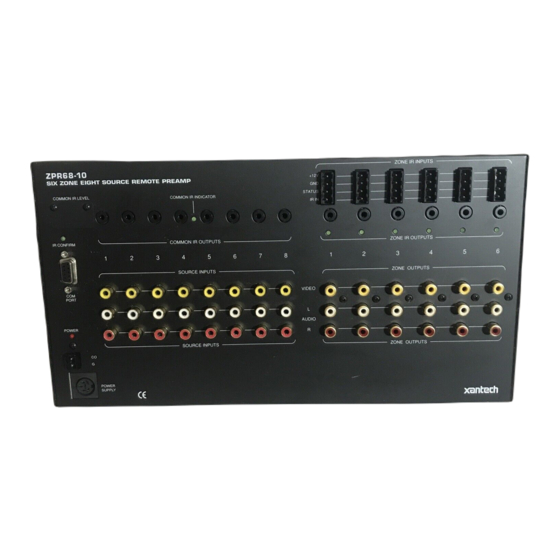
SIX ZONE EIGHT SOURCE REMOTE CONTROL PREAMP
ZPR68-10
SIX ZONE EIGHT SOURCE REMOTE PREAMP
COMMON IR LEVEL
COMMON IR INDICATOR
1 2 3 4 5 6 7 8
H I
LO
1 2 3 4 5 6 7 8
IR CONFIRM
COMMON IR OUTPUTS
1
2
3
4
SOURCE INPUTS
VIDEO
COM
PORT
L
AUDIO
POWER
R
SOURCE INPUTS
CO
G
POWER
SUPPLY
Fig.1 Model ZPR68-10
GENERAL
The ZPR68-10 is an infrared remote controlled audio/video preamp capable of switching eight source inputs
into six separate zone cards for multi-zone, multi-room operation.
• Low noise, low distortion, extended headroom design provides outstanding sonic performance in a highly
versatile multi-room, multi-zone design.
• Each zone has separate Volume, Max. Volume, Mute, Balance, Bass and Treble functions, all installer
adjustable. This permits an "EQ" profile to be created to best compliment the individual acoustics and
preferences of each zone.
• Six IR IN control input ports, one for each zone, allows the connection of any Xantech keypad (except
Model 598), IR receiver, controller, etc., for system control.
• Zone and common IR outputs permit IR control of zone and/or common components using Xantech 282/
283/284/286 series mini emitters or 794/797 interface modules. Each emitter output at the common IR
jacks is individually adjustable for high or low IR level.
• Eight separate line level inputs accommodate audio or audio/video sources such as CD players, AM/FM
tuners, tape decks, satellite receivers, LD players, VCR's, etc.
• Input Level Matching. The input level for each audio source can be trimmed by the installer to prevent
large volume differences when switching between sources.
• A COM PORT, using a female DB9 connector, allows full control and status operations with custom
designed panels or computer programs. It is RS-232 data signal compatible. Refer to Application
Advisory, Volume 2, Number 1, for details. This advisory is available on Xantech's web site at
www.xantech.com and http://www.xantech.com.engineer for updates.
• A GLOBAL function allows the user to gang all zones for whole house control of POWER ON/OFF,
SOURCE SELECTION, BASS, TREBLE, VOLUME and MUTE functions ("party mode"). GLOBAL
operation can be prevented in any given zone by using the MUTE command.
INSTALLATION INSTRUCTIONS
ZPR68-10
+12V
GND
STATUS
IR IN
5
6
7
8
1
2
VIDEO
L
AUDIO
R
ZONE CONTROL - IR INPUTS
ZONE IR OUTPUTS
3
4
5
6
ZONE OUTPUTS
ZONE OUTPUTS
® SYLMAR, CA • MADE IN U.S.A.
A
B
C
ADJ-OFF
A
80
48
10
90
01
1
2
3
4
00
C0
50
D0
41
INPUT
5
6
7
8
40
A0
30
B0
21
GLOBAL
20
E0
70
F0
61
TREBLE
BASS
Z-ADJ
VOL
60
88
18
98
09
MUTE
08
A8
38
B8
29
ON
OFF
28
E8
78
F8
69
E-FLAT
LAST
MAX-V
TRIM
68
C8
58
D8
49
OFF
C-BAL
E1
89
C9
A9
E9
71
19
59
39
79
F1
99
D9
B9
F9
RC68+ PROGRAMMER
Fig. 2 Model RC68+
Handheld Programmer
(available separately)
1
Advertisement
Table of Contents

Related Manuals for Xantech ZPR68-10


Summary of Contents for Xantech ZPR68-10
-
Page 1: Installation Instructions
This permits an "EQ" profile to be created to best compliment the individual acoustics and preferences of each zone. • Six IR IN control input ports, one for each zone, allows the connection of any Xantech keypad (except Model 598), IR receiver, controller, etc., for system control. - Page 2 4. ZONE CONTROL - IR INPUTS. Each zone of the ZPR68-10 is individually controlled through these ports. Three of the four screw terminals on each plug-in connector are for connection, via the standard Xantech 3-wire bus, to any Xantech IR receiver, keypad (except Model 598), or controller.
- Page 3 7. ZONE EXPANSION PORT. This port allows the ZPR68-10 to be linked with an EXP9 expansion module to provide up to 15 zones of operation. The EXP9 includes 9 slots, allowing zone XCARDs (PCB cards) to be added one by one in the field, or purchased already installed from the factory, for zones 7 through 15.
- Page 4 To gain access to the jumpers you will need to remove the top cover as follows. a) Remove power supply plug from the Power Supply jack on the ZPR68-10 (if currently plugged in). b) Remove the five (5) screws on each end of the top cover.
- Page 5 7. TRIM button. Activates the Input Level Trim mode. This allows level trimming of each input on the ZPR68-10 so that all sources will sound equally loud when switching from one source to another (see ADJUSTING INPUT LEVEL TRIM procedure). The TRIM mode will turn off automatically 10 seconds after the last button is pressed, or, it can be instantly defeated by pressing the ADJ-OFF button.
-
Page 6: Installation
NOTES: a) Each zone of the ZPR68-10 can be set to its own individual Group Code. This may be useful when the system requirements so dictate. b) The Code Group Number assigned and preset at the factory for each zone of the ZPR68-10 is 68. - Page 7 To 120 V AC (unswitched) POWER SUPPLY 782-00 Power Loop video thru to Supply ZPR68-10 Video Inputs Plug SAT Rec'rs into (if necessary). 120 V AC (u nswitch ed) To Sat #1 Video OUT To Sat #2 Video OUT Gate...
- Page 8 PA640's. Connect the white-striped side to CO and the other to G. 6. Connect the AUDIO L and R ZONE OUTPUT jacks on the ZPR68-10 to the CH1, CH2, etc., LINE INPUT jacks on each of the PA640 Power Amplifiers.
-
Page 9: Power Supply Considerations
Note: The STATUS or CI (Control Inputs) of the devices must remain connected to the respective zone STATUS and common CO terminals on the ZPR68-10, where used. Also, if you exceed 90 mA on any of these terminals, use a Xantech CC12 Remote Relay Module to reduce the current demand. Refer to the CC12 Installation Instructions, Fig. - Page 10 NOTE: The 782-00 Power Supply has a capacity of 1000 mA. If you have a system that is so extensive that the total current exceeds the 1.8 A limit of the ZPR68-10 by more than 1000 mA, use two 782-00's connected so that two separate +12V DC rails are created.
-
Page 11: Setup Procedures
Fig.6. • Each zone IR IN has a Xantech Key Pad and/or Xantech IR Receiver connected. • For AC power management, six of the common sources are current sensed and two are video sensed by the Gatekeep-IR for ON/OFF status. - Page 12 10 seconds). The Z-ADJ settings are now saved, completing the procedure. Note: In zones using only keypads, it will be necessary to temporarily connect a Xantech IR receiver to make the zone adjustment settings. 8. Repeat steps 1 through 6 for each zone.
-
Page 13: Troubleshooting
2. Adjust VOLUME and other functions as outlined under Zone Operatiaons. Note 1: On older versions of the ZPR68-10, the initial volume at turn-on will be a low, factory set, default level. It will NOT return to the volume level last listened to. All other adjustments will remain as previously set. - Page 14 Check to be sure the source components, amplifiers and speakers are connected and operating correctly. Connect a source directly to one of the power amplifiers (bypassing the ZPR68-10 completely) to verify operation of these components. 2. Most of the zones operate correctly, but one or two do not respond to the RC68 commands.
-
Page 15: Specifications
RC68 Code Group Number assigned to the ZPR68-10 ... 68 Control (CO) & STATUS Outputs ... 12 V @ 10 mA, 9 V @ 90 mA (90 mA is max. current) Max. Total Current Available From +12V, STATUS & CO Terminals ... 1.8 A Power Requirements: ... - Page 16 ZPR68-10 BLOCK DIAGRAM Common Common Level Outputs Common Indicator Source Inputs Buffer (Audio L & R) Source Inputs (Video) SOURCE INPUTS PCB PORT COMMON LOCAL CONTROL CONTROL IR In Common Confirm CO Out Control Data Mute Buffer X 0.5 LMC1982...
Need help?
Do you have a question about the ZPR68-10 and is the answer not in the manual?
Questions and answers