
Related Manuals for Pfeiffer Vacuum DVB 016 PX


Summary of Contents for Pfeiffer Vacuum DVB 016 PX
- Page 1 Operating Instructions Inline Valve pneumatically actuated bellows sealed with position indicator and pilot valve DVB 016–040 PX BP 805 227 BE (0106)
-
Page 2: Product Identification
Product Identification In all communications with Pfeiffer Vacuum, please specify the information on the product nameplate. For convenient reference copy that information into the space provided below. Pfeiffer Vacuum, D - 35614 Asslar Typ: F-No: Nominal voltage Validity This document applies to products with the following part numbers:... -
Page 3: Table Of Contents
Contents Product Identification Validity Intended Use 1 Description 1.1 Overview 1.2 Functional Principle 2 Safety 2.1 Symbols Used 2.2 General Safety Instructions 2.3 Liability and Warranty 3 Technical Data 4 Installation 4.1 Vacuum Connection 4.2 Compressed Air Connection 4.2.1 Compressed Air Inlet 4.2.2 Compressed Air Outlet 4.3 Power Connection 5 Operation... -
Page 4: Description
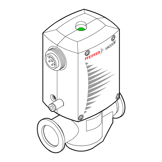
1 Description 1.1 Overview Position indication Connector (visual) (enclosed) Position indicator (electrical) Pneumatic actuator Compressed air outlet Pilot valve Compressed air inlet Instant push-in fittings (enclosed) Vacuum connection DN 16–40 ISO-KF 1.2 Functional Principle When the pilot valve is activated, the inline valve is opened by the pneumatic actuator. -
Page 5: Safety
Communicate the safety instructions to all other users. 2.3 Liability and Warranty Pfeiffer Vacuum assumes no liability and the warranty becomes null and void if end-user or third parties •= disregard the information in this document •= use the product in a non-conforming manner... -
Page 6: Technical Data
3 Technical Data Connection soldered joints Pilot valve Nominal voltage see product nameplate Power Duty cycle 100% Nominal diameter 0.42 Connection soldered joints Electrical position indicator Rating 250 VAC / 25 VA / 0.1 A 50 VDC / 12.5 W / 0.25 A Connection flange DN 16 ISO-KF DN 25 ISO-KF DN 40 ISO-KF Vacuum connection... - Page 7 Stainless steel body 1.4301 Materials Bellows / valve plate 1.4541 / 14301 Pressure spring DN 16+25 ISO-KF 1.4301 DN 40 ISO-KF 1.1200 Seals Shell PBTP Cylinder unit PBTP Protective lid Packing material carton box, PE, PU Stainless steel body 0.44 kg 0.9 kg 1.52 kg Weight...
-
Page 8: Installation
4 Installation 4.1 Vacuum Connection Personnel qualifications Skilled personnel The vacuum connection may only be established by persons who have suitable technical training and the necessary experience or who have been instructed by the end-user of the product. Overpressure 1 bar DANGER Caution: overpressure in the vacuum system >1 bar Injury caused by released parts and harm caused by escaping... -
Page 9: Compressed Air Connection
Vacuum connection Remove the protective lids and install the valve to the vacuum system by means of the small flange fittings. Any installation angle and flow direction may be chosen. Seal with Clamp centering ring ISO-KF connection Protective lid flange 4.2 Compressed Air Connection Personnel qualifications... -
Page 10: Compressed Air Inlet
Plastic threads Caution Caution: plastic thread The plastic thread is damaged by tilting or overturning the instant push-in fitting. •= use the enclosed instant push-in fitting (with extra-long thread) only. •= screw in the instant push-in fitting without tilting it and without exceeding the tightening torque of 0.5 Nm. -
Page 11: Compressed Air Outlet
4.2.2 Compressed Air Outlet Screw in the enclosed instant push-in fitting for exhausting the compressed air if necessary. Push the tube into the instant push-in fitting until the mechanical stop is reached. Check that it is correctly mounted by slightly pulling. Compressed air outlet Compressed air inlet... - Page 12 Preparing the connector Slide the screw fitting, connector housing, and strain relief on the cable. Strain relief Screw fitting Connector housing Seal Washer Hex head screw Skin the cable and mount the insulating sleeves if required. Insulating sleeves (not incuded) Solder the cable.
- Page 13 Tighten the strain relief and insert it (it will catch). Reassemble the connector and tighten the screw fitting (width across 17 mm). hold stationary Plug in the connector and secure it with the union nut. Union nut BP 805 227 BE (0106) DVB 16–40 PX.bet...
-
Page 14: Operation
5 Operation The product is ready for operation as soon as it has been installed. Valve position Valve Compressed Control Position position valve indication closed available deactivated not available activated not available deactivated open available activated DN 16+25 ISO-KF: 1×10 mbar ... -
Page 15: Deinstallation
Opening against a pressure difference ∆p Caution Caution: pressure difference ∆ p V ACU UM ∆ p p + ∆ p Opening With ∆ p >4 bar (DN 16+25 ISO-KF) and ∆ p >2 bar (DN 40 ISO-KF) the valve cannot open. Avoid bigger pressure differences. -
Page 16: Compressed Air Connection
6.2 Compressed Air Connection Personnel qualifications Skilled personnel The compressed air may only be disconnected by persons who have suitable technical training and the necessary experience or who have been instructed by the end-user of the product. Disconnection of the DANGER compressed air line Caution: compressed air... -
Page 17: Vacuum Connection
6.3 Vacuum Connection Personnel qualifications Skilled personnel The vacuum connection may only be disassembled by persons who have suitable technical training and the necessary experience or who have been instructed by the end-user of the product. Possible contamination DANGER Caution: contaminated parts Contaminated parts can be detrimental to health and environment. -
Page 18: Maintenance And Repair
7 Maintenance and Repair Personnel qualifications Skilled personnel All work described in this document may only be carried out by per- sons who have suitable technical training and the necessary experi - ence or who have been instructed by the end-user of the product. Possible contamination DANGER Caution: contaminated parts... -
Page 19: Disassembling The Product
Procedure Maintenance and repair work comprises: 7.1 Disassembling the product 7.2 Checking and cleaning the parts 7.3 Reassembling the product 7.1 Disassembling the Parts Steps Product Adapter Pilot valve ë Electrical position indicator ô Cylinder unit ÷ Bellows ÷ Seals Unscrew the instant push-in fitting(s). - Page 20 Remove the screws of the body. Remove the shell. Remove the visual position indicator. BP 805 227 BE (0106) DVB 16–40 PX.bet...
- Page 21 Remove the wire harness ..from the pilot valve ... from the electrical position indicator Remove the adapter and pilot valve. Pilot valve Adapter BP 805 227 BE (0106) DVB 16–40 PX.bet...
- Page 22 Do only separate the adapter from the pilot valve when removing the latter. Pilot valve Adapter Unscrew the switch clip. Size DN 16 ISO-KF DN 25 ISO-KF DN 40 ISO-KF øB / C×D DN 16 ISO-KF ø4.3/12×1 DN 25 ISO-KF ø5.3/15×1.2 DN 40 ISO-KF ø5.3/15×1.2...
- Page 23 Pull out the parallel pin. DN 16 ISO-KF DN 25 ISO-KF DN 40 ISO-KF ë Pull out the electrical position indicator. Position indicator BP 805 227 BE (0106) DVB 16–40 PX.bet...
- Page 24 ñ Place the valve under a press and secure the cylinder unit. DANGER Caution: prestressed spring Spring forces: DN 16 ISO-KF = 50 N DN 25 ISO-KF = 80 N DN 40 ISO-KF = 175 N Uncontrolled release of the spring can cause physical injuries. Hold the cylinder unit in position while loosening the grub screws.
- Page 25 ò Remove the grub screws. GEFAHR Caution : prestressed spring Spring forces: DN 16 ISO-KF = 50 N DN 25 ISO-KF = 80 N DN 40 ISO-KF = 175 N Uncontrolled release of the spring can cause physical injuries. Hold the cylinder unit in position while loosening the grub screws.
- Page 26 ó Slowly release the press. ô Using a pin, separate the piston and cylinder unit from each other. BP 805 227 BE (0106) DVB 16–40 PX.bet...
- Page 27 õ Remove the pressure spring. ö Remove the bellows. BP 805 227 BE (0106) DVB 16–40 PX.bet...
- Page 28 ÷ Remove the seals. Caution Do not compress the bellows. O-rings included in seal kit. O-ring, FPM øA × B øC × D øE × F DN 16 ISO-KF ø31.47×1.78 ø15.88×2.62 ø6.07×1.78 DN 25 ISO-KF ø44.17×1.78 ø25.07×2.62 ø9.25×1.78 DN 40 ISO-KF ø66.34×2.62 ø39.69×3.53 ø9.92×2.60...
-
Page 29: Checking And Cleaning The Parts
7.2 Checking and Cleaning DANGER the Parts Caution: cleaning with compressed air Flying particles can cause eye injuries. Wear protective glasses. DANGER Caution: cleaning agents Cleaning agents can be detrimental to health and environment. Adhere to the relevant regulations and take the necessary precautions when handling and disposing of cleaning agents ( →... -
Page 30: Reassembling The Product
7.3 Reassembling the Insert the seals. Product Caution Wipe the o-rings with a lint-free cloth slightly moistened with OL090. O-rings be careful to insert them level into the grooves without twisting them.. Lubricate slightly with Dynafat O-rings included in seal kit. O-ring, FPM øA ×... - Page 31 Position the pressure spring. Insert the piston into the cylinder unit and lubricate slightly both as shown below. Be careful to correctly position the piston. Sleeve (only for Piston DN 16 ISO-KF) Lubricate slightly with Dynafat. BP 805 227 BE (0106) DVB 16–40 PX.bet...
- Page 32 Press the cylinder unit into the body. Caution When installing the cylinder unit, make sure to correctly position it on the body. Make sure the connection flange and actuator are correctly positioned relative to each other. BP 805 227 BE (0106) DVB 16–40 PX.bet...
- Page 33 Screw in the grub screws. DN 40 ISO-KF DN 16 ISO-KF M4×6 M4×10 DN 25 ISO-KF M4×6 M4×10 DN 40 ISO-KF M5×6 M5×10 Insert the electrical position indicator. BP 805 227 BE (0106) DVB 16–40 PX.bet...
- Page 34 Secure the electrical position indicator. DN 16 ISO-KF DN 25 ISO-KF DN 40 ISO-KF Mount the switch clip. Caution When tightening the nut, make sure the switch clip is correctly positioned. Tightening torque DN 16 ISO-KF 1.5 Nm DN 25 ISO-KF 2 Nm DN 40 ISO-KF 2 Nm...
- Page 35 Install the visual position indicator. ë Mount the pilot valve on the adapter. Pilot valve Adapter ñ Secure both with the screws. Pilot valve Adapter BP 805 227 BE (0106) DVB 16–40 PX.bet...
- Page 36 ò Plug in the cable socket of the wire harness. Caution Make sure the cable socket properly catches. It produces a "click" noise when properly plugged in and will stay in place when slightly being pulled. ó Bend the cable harness. BP 805 227 BE (0106) DVB 16–40 PX.bet...
- Page 37 ô Insert the appliance connector into the left half of the shell. õ Slide the left half of the shell onto the cylinder unit. ö Check that the visual position indicator is correctly positioned. BP 805 227 BE (0106) DVB 16–40 PX.bet...
- Page 38 ÷ Slide the right half of the shell onto the cylinder unit. ø Screw the shell together. 4× DN 16 ISO-KF 4× DN 25 ISO-KF 4× DN 40 ISO-KF BP 805 227 BE (0106) DVB 16–40 PX.bet...
- Page 39 Screw in the instant push-in fitting(s). Caution Caution: plastic threads The plastic thread can get damaged by tilting or overturning the instant push-in fitting. Screw in the instant push-in fitting without tilting it and without exceeding the tightening torque of 0.5 Nm. Compressed Compressed air outlet...
-
Page 40: Spare Parts
8 Spare Parts When ordering spare parts, always indicate: •= all information on the product nameplate •= description and ordering number according to the spare parts list Caution When installing spare parts, adhere to the safety information in the Maintenance and Repair section of this manual. Adapter Vacuum connection Scope of delivery... - Page 41 Seal kit Vacuum connection Scope of delivery Ordering number DN 16 ISO-KF O-rings FPM75 ø 15.88×2.62 PT130000-T O-rings FPM75 ø 6.07×1.78 O-rings FPM75 ø 31.47×1.78 DN 25 ISO-KF O-rings AN012 ø 9.25×1.78 PT130010-T O-rings FPM75 ø 25.07×2.62 O-rings FPM75 ø 44.17×1.78 DN 40 ISO-KF O-rings FPM75 ø...
-
Page 42: Returning The Product
Contaminated products (e.g. radioactive, toxic, caustic or micro- biological hazard) can be detrimental to health and environment. Products returned to Pfeiffer Vacuum for maintenance, repair, and disposal should preferably be free of harmful substances. Adhere to the forwarding regulations of all involved countries and forwarding companies and enclose a completed declaration of contamination. -
Page 43: Declaration Of Contamination
Declaration of Contamination The service, repair, and/or disposal of vacuum equipment and components will only be carried out if a correctly completed declaration has been submitted. Non-completion will result in delay. This declaration may only be completed (in block letters) and signed by authorized and qualified staff. Description of product Reason for return Type... - Page 44 Emmeliusstrasse 33 D–35614 Asslar Deutschland Tel +49 (0) 6441 802-0 Fax +49 (0) 6441 802-202 info@pfeiffer-vacuum.de Original: German BP 805 227 BD (0106) www.pfeiffer-vacuum.de bp805227be...
Need help?
Do you have a question about the DVB 016 PX and is the answer not in the manual?
Questions and answers