
Subscribe to Our Youtube Channel
Related Manuals for Pfeiffer Vacuum EVB 016 Series


Summary of Contents for Pfeiffer Vacuum EVB 016 Series
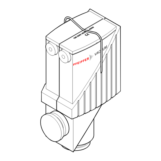
- Page 1 Operating Instructions Angle Valve electromagnetically actuated with automatic voltage adaptation 85 … 248 VAC EVB 016 … 040 MA/MX BP 805 271 BE (0209)
-
Page 2: Product Identification
Product Identification In all communications with Pfeiffer Vacuum, please specify the information given on the product nameplate. For convenient reference copy that information into the nameplate replica below. Pfeiffer Vacuum, D-35614 Asslar Typ: F-No: Nominal voltage Validity This document applies to products with the following part numbers:... -
Page 3: Table Of Contents
Contents Product Identification Validity Intended Use Functional Principle Trade Marks 1 Description 1.1 Operating Modes 1.2 Indication of Positions and Faults 1.3 Position Indicator (in REMOTE mode only) 2 Safety 2.1 Symbols Used 2.2 General Safety Instructions 2.3 Liability and Warranty 3 Technical Data 4 Installation 4.1 Vacuum Connection... -
Page 4: Description
1 Description 1.1 Operating Modes The angle valve has two operating modes: · REMOTE mode Drive via control voltage 15 … 30 VDC. · LOCAL mode Drive via supply voltage 85 … 248 VAC. The operating mode is selected by setting a switch (® 2 12). REMOTE mode In the REMOTE mode, the supply voltage of 85 …... -
Page 5: Indication Of Positions And Faults
1.2 Indication of Positions and Faults Green LED lit = valve open Red LED lit = valve closed Red LED flashing = fault, for instance a temperature overload 1.3 Position Indicator The integrated position indicator allows for polling the valve positions. In the event of a fault, the signal "valve closed"... -
Page 6: Safety
Communicate the safety instructions to all other users. 2.3 Liability and Warranty Pfeiffer Vacuum assumes no liability and the warranty becomes null and void if end-users or third parties · disregard the information in this document ·... - Page 7 Notes BP 805 271 BE (0209) EVB 016 … 040 MA/MX.oi...
-
Page 8: Technical Data
3 Technical Data Connection flange DN 16 ISO-KF DN 25 ISO-KF DN 40 ISO-KF Actuation opening: electromagnetically closing: by pressure spring Supply voltage 85 … 248 VAC Frequency 50 / 60 Hz Power consumption 400 W (max. upon switching on) Pickup-/Holding power 405 / 8.1 W 416 / 8.3 W... - Page 9 Connection flange DN 16 ISO-KF DN 25 ISO-KF DN 40 ISO-KF Conductance 4 l/s 16 l/s 40 l/s Materials housing aluminum (3.2374) or stainless steel (1.4301) inside section 1.4301 and 1.4541 seals shell PAGV 30 Weight aluminum housing 1.3 kg 2.2 kg 4 kg stainless steel housing...
-
Page 10: Installation
4 Installation 4.1 Vacuum Connection Skilled personnel The vacuum connection may only be established by persons who have suitable technical training and the necessary experience or who have been instructed by the end-user of the product. DANGER Caution: overpressure in the vacuum system >1 bar Injury caused by released parts and harm caused by escaping process gases can result if clamps are opened while the vacuum system is pressurized. -
Page 11: Electrical Connection
4.2 Electrical Connection Skilled personnel The electrical connection, in accordance with the VDE 0100 guidelines, may be made only by a licensed electrician, qualified as per VDE 0105. The line cables shall be isolated from the line supply during all electrical work. DANGER Caution: mains voltage Products that are not professionally connected to ground can be... -
Page 12: Setting The Operating Mode Selection Switch
4.2.2 Setting the Operating The operating mode must be selected before the electrical connection is Mode Selection Switch established. If a 15 … 30 VDC control voltage is available, choose REMOTE. Setting the operating mode switch Control voltage 15 ... 30 VDC available? REMOTE mode LOCAL mode... -
Page 13: Connecting The Feeder Line
Œ 4.2.3 Connecting the Feeder Prepare the feeder line. Line Caution The cable must meet the following specifications: · flexible · conductor cross-section 1 mm · 3 poles with protective conductor (P+N+PE) · 5 … 7 mm diameter (for the cable feedthrough to meet the IP 54 specifications) ... -
Page 14: Connecting The Control Cable (For Remote Mode Only)
Œ 4.2.4 Connecting the Control Prepare the control cable (for REMOTE mode only). Cable (for REMOTE Mode Only) Caution The cable must meet the following specifications: · flexible · conductor cross-section 0.75 mm · 4-pole with protective conductor · 5 … 7 mm diameter (for the cable feedthrough to meet the IP 54 specifications) ... -
Page 15: Mounting The Cover
Ž Connect the conductors. Œ 4.2.5 Mounting the Cover Mount the cover. Caution Be careful not to squeeze any cable leads. Mount the clamp again. BP 805 271 BE (0209) EVB 016 … 040 MA/MX.oi... -
Page 16: Operation
5 Operation The product is ready for operation as soon as it has been installed. DANGER Caution: bursting pressure Overpressures >3 bar (e.g. in the event of an explosion) can cause the inside section and housing to burst. This could result in injuries caused by catapulted parts and health damages due to leaking process gases. - Page 17 Pressure range 1×10 mbar … 1.3 bar (absolute) Pressure difference Dp in Caution closing direction Caution: pressure difference Dp bar p + D p At Dp >1.3 bar the valve may no longer be tight. Avoid pressure differences Dp >1.3 bar. Pressure difference Dp in opening direction Caution...
-
Page 18: Deinstallation
6 Deinstallation 6.1 Electrical Connection Skilled personnel The electrical connection, in accordance with the VDE 0100 guide- lines, may be made only by a licensed electrician, qualified as per VDE 0105. The line cables shall be isolated from the line supply during all electrical work. -
Page 19: Vacuum Connection
6.2 Vacuum Connection Skilled personnel The vacuum connection may only be disassembled by persons who have suitable technical training and the necessary experience or who have been instructed by the end-user of the product. DANGER Caution: contaminated parts Contaminated parts can be detrimental to health and environment. Before beginning to work, find out whether any parts are contaminated. -
Page 20: Troubleshooting
7 Troubleshooting Troubleshooting Problem Valve does not Valve leaks Red LED flashing stay open Cause Position indicator Valve seat dirty or Temperature gasket defective overload dirty Valve actuator Ambient tempe- blocked rature too high Remedy Cool valve, keep ambient tem- perature <... -
Page 21: Maintenance
8 Maintenance ® 2 22 ® 2 23 ® 2 24 ® 2 25 ® 2 26 ® 2 27 Maintenance work: • Replacing the fuse and the fuse holder • Replacing the electronics • Replacing the gaskets • Replacing the hoisting magnet or the inside section •... - Page 22 Removing the cover Œ Remove the clamp. Remove the cover. Removing the fuse holder Ž together with the fuse Remove the fuse holder together with the fuse. BP 805 271 BE (0209) EVB 016 … 040 MA/MX.oi...
- Page 23 Removing the shell Remove the connectors. Pierce the stopper with a pointed tool and pull it out. ‘ Loosen and remove the shell screws. BP 805 271 BE (0209) EVB 016 … 040 MA/MX.oi...
- Page 24 ’ Remove the shell parts. Caution When reassembling the product: insert the electronics in the guide notch of the shell parts, be careful not to squeeze any cables. Disassembling the electronics “ Unscrew the position indicator. The photoelectric barrier must not be dirty. Cross-recess screw Washer Position indicator...
- Page 25 • Unsolder the red and the blue wire of the electronics. Do not inhale the vapors. Soldering iron blue Check the LED seal and replace it as required. Cemented LED seal BP 805 271 BE (0209) EVB 016 … 040 MA/MX.oi...
- Page 26 Removing the hoisting magnet together with the inside section Remove the hoisting magnet together with the inside section. DANGER Caution: prestressed spring Spring forces: DN 16 =35 N DN 25 =60 N DN 40 =105 N Uncontrolled releasing of the spring can cause injuries. When loosening the Torx screws, counterhold the hoisting magnet.
- Page 27 Separate the hoisting magnet from the inside section Loosen the inside section. Caution Since the inside section is secured with Loctite 241, it is difficult to loosen it. Carefully retract Size 6 the bellow. Size 10 Hold stationary. Remove the inside section and the spring. Reassembly: secure with loctite.
-
Page 28: Spare Parts
9 Spare Parts When ordering spare parts, always indicate: · all information on the product nameplate · description and ordering number according to the spare parts list Mounting the spare parts ® 2 21. Fuses Ordering numbers DN 16 ISO-KF: PT130002-T (ø5 × 20, 2 A, super slow) DN 25 ISO-KF: PT130002-T (ø5 ×... - Page 29 Bellows assembly comprising bellows complete, (without spring), Loctite 241, 6 stoppers Ordering numbers DN 16 ISO-KF: PT130039-T DN 25 ISO-KF: PT130044-T DN 40 ISO-KF: PT130045-T BP 805 271 BE (0209) EVB 016 … 040 MA/MX.oi...
-
Page 30: Returning The Product
Contaminated products (e.g. radioactive, toxic, caustic or micro- biological hazard) can be detrimental to health and environment. Products returned to Pfeiffer Vacuum should preferably be free of harmful substances. Adhere to the forwarding regulations of all involved countries and forwarding companies and enclose a duly completed declaration of contamination. -
Page 31: Declaration Of Contamination
Declaration of Contamination The service, repair, and/or disposal of vacuum equipment and components will only be carried out if a correctly completed declaration has been submitted. Non-completion will result in delay. This declaration may only be completed (in block letters) and signed by authorized and qualified staff. Description of product Reason for return Type... - Page 32 Emmeliusstrasse 33 D–35614 Asslar Deutschland Tel +49 (0) 6441 802-0 Fax +49 (0) 6441 802-202 info@pfeiffer-vacuum.de Original: German BP 805 271 BD (0201) www.pfeiffer-vacuum.de bp805271be...
Need help?
Do you have a question about the EVB 016 Series and is the answer not in the manual?
Questions and answers