
Related Manuals for Pfeiffer Vacuum UHV 016 CU


Summary of Contents for Pfeiffer Vacuum UHV 016 CU
- Page 1 A P A S S I O N F O R P E R F E C T I O N UHV 016 ... 063 CU All-Metal Angle Valve, manually operated, bellows sealed, metal valve seat seal Operating Instructions...
-
Page 2: Product Identification
Product Identification In all communications with Pfeiffer Vacuum, please specify the information on the product nameplate. For convenient reference copy that information into the space provided below. Pfeiffer Vacuum, D-35614 Asslar Typ: F-No: Validity This document applies to products with part numbers... -
Page 3: Table Of Contents
Contents Product Identification Validity Intended Use 1 Description 1.1 Overview 1.2 Functional Principle 2 Safety 2.1 Symbols Used 2.2 Personnel Qualifications 2.3 General Safety Instructions 2.4 Liability and Warranty 3 Technical Data 4 Installation 4.1 Installation 4.1.1 Space Requirements 4.1.2 Flange Connection 5 Start-Up 5.1 Bakeout 5.2 Bringing the Valve Plate Into the Defined Position... -
Page 4: Description
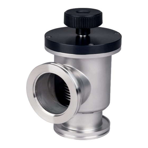
1 Description 1.1 Overview Rotary knob (enclosed) Mark on the valve housing Adjustment ring Leak detection bore Hex socket set screw Bellows Valve plate base Valve plate Sealing edge CF flange DN 16 ... 63 CF-R (rotatable) 1.2 Functional Principle The sealing effect of the Angle valve is achieved by pressing the valve plate against the sealing edge. -
Page 5: Personnel Qualifications
Communicate the safety instructions to all other users. 2.4 Liability and Warranty Pfeiffer Vacuum assumes no liability and the warranty becomes null and void if the end-user or third parties • disregard the information in this document •... -
Page 6: Technical Data
3 Technical Data Connection flanges, rotatable UVH 016 CU DN 16 CF-R UVH 040 CU DN 40 CF-R UVH 063 CU DN 63 CF-R Installation angle Flow direction Tightness 1×10 mbarl/s Pressure range 1×10 mbar … 4 bar (absolute) Bursting pressure 8 bar Conductance UVH 016 CU... - Page 7 Dimensions [mm] ø 62 UVH 016 CU AF 8 DN 16 CF-R (rotatable) DN 16 CF-R (rotatable) UVH 040 CU ø 62 AF 17 DN 40 CF-R (rotatable) DN 40 CF-R (rotatable) UVH 063 CU ø74 AF 22 DN 63 CF-R (rotatable) ø100 DN 63 CF-R (rotatable) BP 5275 BEN...
-
Page 8: Installation
4 Installation Caution Caution: vacuum component Dirt and damages impair the function of the vacuum component. When handling vacuum components, take appropriate measures to ensure cleanliness and prevent damages. Caution Caution: dirt sensitive area Touching the product or parts thereof with bare hands increases the desorption rate. -
Page 9: Flange Connection
4.1.2 Flange Connection Hex nut Washer CF flange Hex head screw Seal Protective lid Keep the protective lids. Flange seals Flange Seal Pieces Ordering number DN 16 CF Copper PF 501 401-T Copper, silver-plated PF 501 501-T DN 40 CF Copper PF 501 404-T Copper, silver-plated... -
Page 10: Start-Up
5 Start-Up 5.1 Bakeout It is good practice to bake out new valves and valves the inner parts of which have been exposed to atmosphere for some time, e.g. with a heating jacket. DANGER DANGER: hot surface Touching the hot surface (>55 °C) can cause burns. Do not touch the hot surface. -
Page 11: Bringing The Valve Plate Into The Defined Position
5.2 Bringing the Valve Plate Using a ring wrench, turn the hex head until mark on the adjustment ring is in Into the Defined Position line with the mark on the valve housing. 90° Mark on valve housing The valve is closed and ready for use now. BP 5275 BEN (2010-10) UVH_016-063_CU.oi... -
Page 12: Operation
Check that the valve is tight. If it is not yet tight, gradually increase the closing torque in small steps (Δα ≈ 5°) until the valve is tight. Do not exceed the maximum closing torque. Closing torque minimum maximum UHV 016 CU 2 Nm 10 Nm UHV 040 CU 8 Nm 30 Nm... - Page 13 Operating temperature ≤55 °C Position the valve plate on the sealing edge by turning the rotary knob clockwise until an increased resistance can be felt. Remove the rotary knob. Turn until an increased resistance can be felt enclosed Close the valve by turning the hex head clockwise with a ring wrench until mark on the adjustment ring is in line with the mark on the valve housing.
- Page 14 Check that the valve is tight. If it is not yet tight, keep gradually turning the hex head in small steps (Δα ≈ 5°) until the valve is tight. However, do not turn the hex head any further when mark (α...
-
Page 15: Opening The Angle Valve
6.2 Opening the Angle Valve The maximum opening of the valve is limited by a mechanical stop. Open the valve by turning the hex head counter-clockwise with a ring wrench until the resistance decreases. Remove the ring wrench. Use the ring wrench only temporarily °C >55 °C... -
Page 16: Deinstallation
7 Deinstallation DANGER DANGER: contaminated parts Contaminated parts can be detrimental to health and environment. Before beginning to work, find out whether any parts are contami- nated. Adhere to the relevant regulations and take the necessary precautions when handling contaminated parts. Caution Caution: vacuum component Dirt and damages impair the function of the vacuum component. -
Page 17: Maintenance
8 Maintenance 8.1 Bakeout The valve is baked in order for its inner parts to be degassed. Undesirable gases can thus be pumped. The pumping time is reduced and the final pressure is reached faster. It is good practice to bake out valves after cleaning (→ 23) and when their inner parts have been exposed to atmosphere for some time, e.g. - Page 18 Place the valve on the rotary knob and carefully unscrew the valve plate by turning it clockwise with the supplied tool. Supplied tool Valve plate Take out the valve plate with the supplied tool. Caution Caution: sealing edge The sealing edge can easily get damaged by a tool or the valve plate.
-
Page 19: Installing A New Valve Plate
Sealing edge Carefully slide the tool Valve plate under the valve plate. Do not damage the seal- ing edge. Valve plate Lift the valve plate and take it out with the tool. Tool 8.2.2 Installing a New Valve Using the supplied tool, place the valve plate on the threaded tapped hole of Plate the valve plate base. -
Page 20: Adjusting The Sealing Elements
Carefully screw the valve plate in by turning it clockwise with the supplied tool. Fasten it hand-tight. Hand-tight 8.3 Adjusting the Sealing After the valve plate has been replaced, the sealing elements (valve plate and sealing edge) must be adjusted. Elements Position the valve plate on the sealing edge by carefully turning the rotary knob clockwise until an increased resistance can be felt. -
Page 21: Adjustment Ring Setting
Close the valve by turning the ring wrench clockwise for an angle of α α Angle valve α UHV 016 CU 15° UHV 040 CU 20° UHV 063 CU 30° Preliminary information. Open the valve by turning the ring wrench counter-clockwise until the resistance decreases. - Page 22 Check tightness. If the valve is not tight, turn the ring wrench clockwise in small steps (Δα ≈ 5°), until the valve is tight. Caution Caution: α > 30° At α > 30°, the 90° mark on the adjustment ring can no longer be used (→...
-
Page 23: Cleaning The Angle Valve
Lock the adjustment ring in this position by fastening the hex socket screw with the allen wrench. AF 1.5 8.5 Cleaning the Angle DANGER Valve DANGER: cleaning agents Cleaning agents can be detrimental to health and environment. Adhere to the relevant regulations and take the necessary precautions when handling and disposing of cleaning agents. -
Page 24: Repair
9 Repair Defective angle valves cannot be repaired. 10 Spare Parts When ordering spare parts, always indicate: • all information on the product nameplate • description and ordering number according to the spare parts list Valve plate Flange Sealing plate Pieces Ordering number DN 16 CF... -
Page 25: Accessories
Contaminated products (e.g. radioactive, toxic, caustic or biological hazard) can be detrimental to health and environment. Products returned to Pfeiffer Vacuum should preferably be free of harmful substances. Adhere to the forwarding regulations of all in- volved countries and forwarding companies and enclose a duly com- pleted declaration of contamination Form under www.pfeiffer-vacuum.net... -
Page 26: Disposal
14 Disposal DANGER DANGER: contaminated parts Contaminated parts can be detrimental to health and environment. Before beginning to work, find out whether any parts are contami- nated. Adhere to the relevant regulations and take the necessary precautions when handling contaminated parts. WARNING WARNING: substances detrimental to the environment Products or parts thereof (mechanical and electric components,... - Page 27 Notes BP 5275 BEN (2010-10) UVH_016-063_CU.oi...
- Page 28 A P A S S I O N F O R P E R F E C T I O N Pfeiffer Vacuum stands for innovative and custom Leading. Dependable. vacuum solutions worldwide. For German engineering art, Customer Friendly. competent advice and reliable services.
Need help?
Do you have a question about the UHV 016 CU and is the answer not in the manual?
Questions and answers