Table of Contents
Advertisement
Quick Links
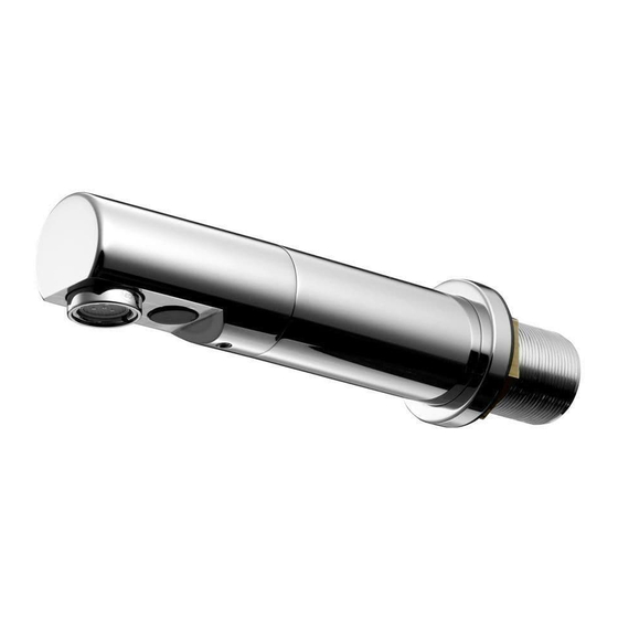
Sensorflow 21 compact panel
mounted 150 & 230 reach spouts
Ø10
650mm
Ø15
Ø10
570mm
Ø15
Ø15
103
86
Ø15
Important:
1. Electrical connection: mains electric powered versions of these
products must be connected to a continuous permanent power supply.
2. Sensor protector: this black-out lens cover should only be removed
from the sensor after completing installation & at least 10 seconds
after powering up.
See page 3 for more details.
BEFORE CONNECTION, FLUSH WATER THROUGH PIPEWORK TO REMOVE
ALL DEBRIS ETC. WHICH COULD DAMAGE THE VALVE MECHANISM
INSTALLER:
After installation please pass this instruction booklet to user
Ø50
M33 x 1.5
max.30
Ø50
M33 x 1.5
max.30
Ø15
61
Ø15
IMPORTANT
Ø38
150
Ø38
230
40
116
INSTALLATION
INSTRUCTIONS
150 Reach:
A4845AA,
A4846AA/GN &
A4847AA/GN
230 Reach:
A4848AA,
A4849AA/GN &
A4850AA/GN
67
Advertisement
Table of Contents

Related Manuals for Armitage Shanks Sensorflow 21 compact panel mounted 150 reach spout


Summary of Contents for Armitage Shanks Sensorflow 21 compact panel mounted 150 reach spout
- Page 1 INSTALLATION Sensorflow 21 compact panel INSTRUCTIONS mounted 150 & 230 reach spouts Ø50 Ø10 M33 x 1.5 150 Reach: A4845AA, Ø38 A4846AA/GN & 650mm A4847AA/GN Ø15 max.30 Ø50 Ø10 M33 x 1.5 230 Reach: Ø38 A4848AA, A4849AA/GN & 570mm A4850AA/GN Ø15 max.30 Ø15...
-
Page 2: Table Of Contents
TABLE OF CONTENT IMPORTANT PRE-INSTALLATION NOTES ........3 PRODUCT BOX CONTENTS ............4 SUPPLY CONDITIONS ..............5 WATER REGULATIONS ..............5 INSTALLATION GUIDE ..............6 MOUNTING ......................6 PLUMBING OVERVIEW ..................7 ELECTRICAL CONNECTION ................9 TAP OPERATION ................14 SENSOR CONFIGURATION ............ -
Page 3: Important Pre-Installation Notes
IMPORTANT PRE-INSTALLATION NOTES MAINS ELECTRICAL POWER SUPPLY Mains powered Sensor Operated Products must be connected to a (fused / switched) continuous permanent power supply. This can be by a fused spur or a fused & switched spur. Installing a switch will permit easier future maintenance of the electrical system. -
Page 4: Product Box Contents
PRODUCT BOX CONTENTS 1x copper inlet pipe 1x Sensorflow 21 compact spout with integral sensor Regulated PCA outlet pre-fitted. See section 8 2x Couplers G 1/2“ female thread to 15 mm compression 1x Spout mounting kit 1x Outlet key 1x Flow straightener moulding 1x Velcro... -
Page 5: Supply Conditions
Use of an appropriate temperature reduction device (i.e. tee pattern thermostat) is recommended to ensure delivery of safe hot water from this product. Armitage Shanks recommends the use of a under basin thermostatic valve A5900AA, to purchase please contact our customer care team. -
Page 6: Installation Guide
INSTALLATION GUIDE Before connection, flush water through pipe-work to remove all debris etc. to prevent damage to the valve mechanism. THEN ENSURE WATER SUPPLIES HAVE BEEN ISOLATED. Mounting DRILL PANEL HOLE Ø35 MIN, Ø40 MAX INSTALLATION HEIGHT: we recommend the spout outlet be positioned approximately 150-200mm above the basin or worktop (which ever is higher). -
Page 7: Plumbing Overview
INSTALLATION GUIDE continued… Spout inlet pipe Ø 10mm Inlet elbow Plumbing Overview 15 to 10mm compression Once the spout has been secured to the panel, consideration should be given to installing & positioning of the inline valves. A typical plumbing installation example is shown here. - Page 8 INSTALLATION GUIDE continued… 5. To fit inlet elbow cont: Slip the larger compression nut & olive onto a short length of Ø15mm supply pipe. Push the supply pipe into the elbow up to the shoulder. Slide the olive up to the elbow & tighten the compression nut with a 24mm A/F spanner.
-
Page 9: Electrical Connection
INSTALLATION GUIDE ELECTRICAL… ELECTRICAL SAFETY IEE (BS 7671) In the interest of electrical safety, ensure all wiring conforms to the latest standard UK IEE Wiring Regulations. Always ensure mains power supply is switched off before commencing any electrical connection work. Electrical connection Connection of this product to mains black... - Page 10 INSTALLATION GUIDE ELECTRICAL… INSTALLATION GUIDE continued… Electrical connection continued… MAINS AC ENSURE MAINS POWER SUPPLY IS SWITCHED OFF BEFORE COMMENCING PLUS LINK(S) 13. Open the PSU case by unscrewing 4x posi-drive screws. 14. The lid & seal should separate from the PSU case.
- Page 11 INSTALLATION GUIDE ELECTRICAL… Each type of PSU is identified by this coloured dot system: MAINS MAINS AC PLUS LINK(S) BLUE LINK BATTERY GREEN MAINS AC -SOLO BATTERY -SOLO 6V Lithium CR-P2 GREEN 230 V 24. Remove the pre-split grommet from the PSU lid. Slide the grey sensor cable into this grommet.
- Page 12 INSTALLATION GUIDE continued… Electrical connection continued… 28. Mains power cable (not supplied) should be flexible 3A rated (multi-strand) 2 core cable. Prepare the cable for connection into the PCB by carefully stripping back the outer sheath by about 100mm. Strip the wire ends back by about 5mm.
- Page 13 INSTALLATION GUIDE continued… Electrical connection continued… A pair of self-adhesive Velcro-type pads are provided. Attach one to the side of the PSU case & the other to a suitable location on the rear of the mounting panel. Ensure the selected location does not stretch/stress the cables.
-
Page 14: Tap Operation
INSTALLATION GUIDE continued… Electrical connection continued… Example above of an installation where PSUs are all mains versions. Sensor taps stickers: To complete the installation, 2 stickers are provided which can be stuck onto a wall or panel in close proximity to this product to advise the end user that this product sensor operated. -
Page 15: Sensor Configuration
SENSOR CONFIGURATION Upon completion of installation, both plumbing & electrical, the product can be powered up. The product is designed as “plug & play” system. So to get the product up & running quickly, follow these simple steps: • Switch on power supply DURING SETTING UP •... -
Page 16: Detection Range Adjustment
DETECTION RANGE ADJUSTMENT Follow steps 1 to 4, cover the sensor 5 Sec. with a finger for 5 sec. Remove finger after the first confirmation flush. Assuming previous setting was factory 2 Sec. set, the next option will be set at the range plus 20%, LED will give 3 flashes. -
Page 17: Hygiene Flush (Automatic)
Maintenance continued… • Disconnect the solenoid valve cables • Remove the 3 screws holding the coil. • Lift off the coil assembly. • Locate the diaphragm (inside the valve body). • Clean out the pilot hole(s) – use a thin gauge fuse wire (or similar). If diaphragm is damaged it should be replaced. -
Page 18: Service Valve
Maintenance continued… Once in the configuration menu, cover the sensor with a finger for 10 sec. There will be a first 2 sec confirmation flush at 5 sec & a second flush at 10 sec. Remove finger immediately, observe the sensor, a LED will flash once to indicate 24-hour flush is activated (ON) To switch off the 24 hour flushing cycle, repeat this sequence, LED will flash twice to confirm OFF. -
Page 19: Spare Parts
SPARE PARTS For more information on spare parts why not visit our spare website: fast www.fastpart-spares.co.uk. Or contact customer care... -
Page 20: Cleaning Chrome Surfaces
For more information about our products & spares visit our websites: www.idealstandard.co.uk Armitage Shanks pursues a policy of continuing improvements in design & per- formance of its products. This right is therefore reserved to vary specification without notice. Partial or total reproduction or copying of this manual without our AFTER SALES NON RESIDENTIAL HEL- permission is prohibited.
Need help?
Do you have a question about the Sensorflow 21 compact panel mounted 150 reach spout and is the answer not in the manual?
Questions and answers