Summary of Contents for Armitage Shanks Sensorflow 21
Page 1
INSTALLATION 
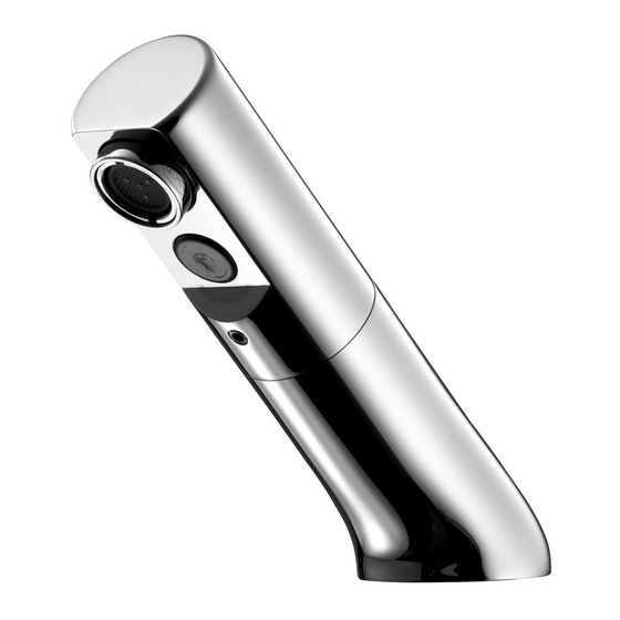
Sensorflow 21 compact spout INSTRUCTIONS A4851AA, A4852AA & A4853AA Ø15 45° Ø48 Ø15 max.50 Ø15 M28 x 1.5 Ø8 Ø15 Important: 1. Electrical connection: mains electric powered version of this product must be connected to a continuous permanent power supply.
Sensorflow 21 compact basin spout with integral sensor This compact angled basin mount Sensorflow 21 electronic product is designed for water economy & hygienic “no-touch” operation. The spout is operated by the integral infrared sensor which is triggered by hand movement in the sensing region.
IMPORTANT PRE-INSTALLATION NOTES MAINS ELECTRICAL POWER SUPPLY Mains powered Sensor Operated Products must be connected to a (fused / switched) continuous permanent power supply. This can be by a fused spur or a fused & switched spur. Installing a switch will permit easier future maintenance of the electrical system.
WATER REGULATIONS The fittings covered by this installation and maintenance instruction should be installed in accordance with the water regulations published in 1999*, therefore Armitage Shanks would strongly recommend that these fittings are installed by a professional installer *A guide to the Water Supply (Water Fittings) Regulations 1999 and the Water Byelaws 2000, Scotland is published by WRAS (Water Regulations Advisory Scheme) Unit 13, Willow Road, Pen-y-Fan Industrial Estate, Crumlin, Gwent, NP11 4EG.
INSTALLATION GUIDE Before connection, flush water through pipe-work to remove all debris etc. to prevent damage to the valve mechanism. THEN ENSURE WATER SUPPLIES HAVE BEEN ISOLATED. Mounting 1. Remove the spout mounting kit if already assembled to the spout tail. Ensure the basin rubber washer (smaller diameter one) is in place as shown.
Plumbing Overview Spout inlet pipe Ø8mm Once the spout has been secured to the ba- sin, consideration should be given to install- ing & positioning of the inline valves. Inlet adaptor A typical plumbing installation example is shown here. The water is being supplied from 15 to 8mm below, but can be from any direction.
Page 8
5. To fit inlet adaptor cont: Slip the larger compression nut & olive onto a short length of Ø15mm supply pipe. Push the supply pipe into the adaptor up to the shoulder. Slide the olive up to the adaptor & tighten the compression nut with a 24mm A/F spanner. Hold the adaptor steady with a 22mm A/F spanner.
ELECTRICAL SAFETY IEE (BS 7671) In the interest of electrical safety, ensure all wiring conforms to the latest standard UK IEE Wiring Regulations. Always ensure mains power supply is switched off before commencing any electrical connection work. NOTE: Children must not be allowed to clean or maintain this product black Electrical connection...
Page 10
Electrical connection continued… ENSURE MAINS POWER SUPPLY IS SWITCHED OFF BEFORE COMMENCING 13. Open the PSU case by unscrewing 4x MAINS AC posi-drive screws. PLUS LINK(S) 14. The lid & seal should separate from the PSU case. 15. For battery version, orientate the battery correctly &...
Page 11
Each type of PSU is identified by this coloured dot system: MAINS MAINS AC PLUS LINK(S) BLUE LINK BATTERY GREEN MAINS AC -SOLO BATTERY -SOLO 6V Lithium CR-P2 GREEN 230 V 24. Remove the pre-split grommet from the PSU lid. Slide the grey sensor cable into this grommet.
Page 12
Electrical connection continued… 28. Mains power cable (not supplied) should be flexible 3A rated (multi-strand) 2 core cable. Prepare the cable for connection into the PCB by carefully stripping back the outer sheath by about 100mm. Strip the wire ends back by about 5mm. PCB connection: the appropriate wires of the mains cable should connected to the appropriate termi- nal on the block.
Page 13
Electrical connection continued… A pair of self-adhesive Velcro-type pads are provided. Attach one to the side of the PSU case & the other to a suitable location on the rear of the mounting panel. Ensure the selected location does not stretch/stress the cables.
TAP OPERATION Sensorflow 21 products use an Infrared Sensor to activate the system. The sensor is triggered by something reflective (normally hand movement) in the Sens- ing Region.
SENSOR RANGING If the Sensor detects a strong reflection (or similar), the spout will turn on and off intermittently with no one present (Pulsing On / Off). In the unlikely event that this does happen, the Sensing Range must be reduced.
OUTLET OPTIONS This product comes with two outlets one fitted & the second supplied in a bag. The product is factory fitted with a laminar PCA regulated outlet which is secured within an anti-vandal (AV) housing. Unregulated full-flow flow straightener 0.5 bar l/min (SUPPLIED LOOSE)
Maintenance continued… • Remove the 3 screws holding the coil. • Lift off the coil assembly. • Locate the diaphragm (inside the valve body). • Clean out the pilot hole(s) – use a thin gauge fuse wire (or similar). If diaphragm is damaged it should be replaced. •...
Maintenance continued… A brief summary of how to navigate the programming unit is as follows: Handunit ON Navigate to Menu 4 PARAMETER SENSOR 2013 (Enter) MENU 4.1 HAND-WASH (Enter) AUTO-RINSE FREQUENCY: OFF ARROW UP (To required Delay time) (Enter). Recommended: 6 or 12 hours. AUTO-RINSE DURATION: (15 sec default) ARROW UP or DOWN (To required Run Time).
The drawings & diagrams contained in this manual are to be consid- RESIDENTIAL FAX ered approximate & are provided for information only. 0870 122 8282 E-MAIL Armitage Shanks is a division of Ideal Standard (UK) Ltd aftersalesnonresidential@idealstandard.com Armitage Shanks The Bathroom Works, National Avenue 0522 / A 866 771...