Table of Contents
Advertisement
Quick Links
Markwik 21+ Sensor operated
thermostatic mixers
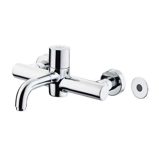
A6684AA Markwik 21+ panel moun-
ted mixer, sensor operated – timed
flow (demountable) with removable
spout & Armitage Bioguard outlet.
Important:
1. Electrical connection: these mains powered sensor operated
products must be connected to a continuous permanent power supply.
2. Sensor protector: this black-out lens cover should only be removed from the
sensor after completing installation & at least 20 seconds after powering up.
See page 3 for more details.
BEFORE CONNECTION, FLUSH WATER THROUGH PIPEWORK TO REMOVE
ALL DEBRIS ETC. WHICH COULD DAMAGE THE VALVE MECHANISM
INSTALLER:
After installation please pass this instruction booklet to user
A6737AA Markwik 21+ panel moun-
ted mixer, sensor operated – timed
flow (demountable) with fixed
spout & Armitage Bioguard outlet
IMPORTANT
INSTALLATION
INSTRUCTIONS
Now with
Armitage
Bioguard
Helping to prevent
the spread of
pseudomonas
bacteria
Advertisement
Table of Contents

Related Manuals for Armitage Shanks A6684AA


Summary of Contents for Armitage Shanks A6684AA
- Page 1 Armitage Bioguard Helping to prevent the spread of pseudomonas bacteria A6684AA Markwik 21+ panel moun- A6737AA Markwik 21+ panel moun- ted mixer, sensor operated – timed ted mixer, sensor operated – timed flow (demountable) with removable flow (demountable) with fixed spout &...
-
Page 2: Table Of Contents
TABLE OF CONTENT TABLE OF CONTENT ....................2 IMPORTANT PRE-INSTALLATION NOTES ............. 3 DESCRIPTION ....................4 PRODUCT BOX CONTENTS ..................5 TIMED FLOW MIXER DIMENSIONS ............6 WATER SUPPLY CONDITIONS ................. 7 WATER REGULATIONS ................. 7 INTRODUCTION ..................... 7 SUPPLY PRESSURE REQUIREMENTS ............7 HEALTHCARE ESTABLISHMENTS .............. -
Page 3: Important Pre-Installation Notes
IMPORTANT PRE-INSTALLATION NOTES MAINS ELECTRICAL POWER SUPPLY Mains powered Sensor Operated Products must be connected to a (fused / switched) continuous permanent power supply. Connection to an interrupted power supply intended to stop electrical consumption in an unused facil- ity, may adversely affect this sensor product and is therefore not recommended. Each time the power supply is reinstated the product briefly enters reprogramming mode. -
Page 4: Description
These Markwik 21+ products permit quick & easy removal of the mixer. The spout can also be removed for cleaning, disinfection & maintenance purposes on mixer A6684AA. Dry testing & protective caps These products are delivered to our customers in a dry state. -
Page 5: Product Box Contents
PRODUCT BOX CONTENTS Factory fitted protective end caps should be removed Fixing kit for mounting mixer. Includes 2 off each: back plates, o-rings, slip 1x Markwik 21+ mixer body with lock shield fitted washers & back-nuts. 1x Sensor kit 1x Velcro pad set complete 2x Couplers G1/2”... -
Page 6: Timed Flow Mixer Dimensions
Timed Flow Mixer Dimensions In healthcare applications the height of the xation holes above the “waste appliance” should be selected to create the recommended “activity space” as de ned in HBN 00-10 Part C, typically 150mm – 200mm for a basin and 250mm – 300mm for a surgeon’s scrub up trough sensor may be mounted either side of the fitting... -
Page 7: Water Supply Conditions
Water regulations The fittings covered by this installation and maintenenance instruction should be installed in accordance with the Water Regulations published in 1999*, therefore Armitage Shanks would strongly recommends that these fittings are installed by a professional installer. *A guide to the Water Supply (Water Fittings) Regulations 1999 and the Water Byelaws 2000, Scotland is pub-... -
Page 8: Installation: Fixation
INSTALLATION: FIXATION These mixers are designed to be panel mounted on a duct wall of maximum panel thickness 27mm. For thicker panels the rear of the panel will require counter bores of 62mm or greater around the fixation holes. Cut two holes of 30mm diameter, horizontally aligned to 200mm centres in the wall. (See figure 1 for height positioning of the fitting body over a “waste appliance”) The sensor will require a hole of 35mm positioned as indicated in either fig4. - Page 9 First refer to section 4. Supply conditions. supply pipes A typical example of an installation of a proximity mixer is shown (from above) water here as a guide. In this example, the water supply pipes are pro- flow vided from above (this usually permits better drain down of pipes). Supplies can be from any direction.
- Page 10 Installation: plumbing continued… IMPORTANT: Ensure in-line servicing valve should be orientated the arrows on the to permit easy access for maintenance valves bodies match supply pipes the direction of (from above) the water flow. FLOW length of 15mm copper tails will define service valve position, ideally adjacent to an access panel Connect water supply pipes to the ser-...
-
Page 11: Flushing
Flushing Important! Small indent on the purging kit must be aligned towards the front of the inlet. IMPORTANT NOTE: Before operating the product, it is strongly recommended to flush the pipe work to remove any residues or debris remaining after installation. A purge kit is available for this purpose. (See 15) The purging kit also provides the facility to obtain water supply temperatures at the inlets Safety Note: Care should be taken when carrying out the following procedure to avoid contact with hot water and hot surfaces. -
Page 12: Installation: Electrical
INSTALLATION: ELECTRICAL Connection of this product to mains solenoids cable from power supply should be undertaken by a sensor competent person and should conform to (red & black) IEE Wiring Regulations. A typical example of an installation of a prox- solenoid linking cable (red &... - Page 13 Installation: electrical continued… Locate the end of the red & black cable which is attached to the rear of the sensor. Cable length is 750mm. Connect this cable to the spade connectors shown on connect sensor the link cable. Observe + and – Ensure red is connected cable onto to red &...
- Page 14 Installation: electrical continued… IMPORTANT: Ensure terminal block screws are firmly tightened & clamp the wires securely. Note earth connection is not required to PCB Locate the end of the second cable (grey with black line) which is attached to the rear of the sensor (cable end has connector fitted, length is 750mm).
-
Page 15: Operation & Sensor Adjustment
OPERATION & SENSOR ADJUSTMENT Operation Both mixers are operated when the user places a hand in the detection zone. Flow will then continue for a preset time of 60 seconds and then stop automatically. The preset time can be adjusted by following the procedure outlined in the section on programming the sensor below. detection zone Figure 16... -
Page 16: Commissioning And Audits
PROGRAMMING THE SENSOR CONTINUED Step 2 Run Time Adjustment While the sensor LED is flashing, hold hand near to sensor (30 - 50mm), The sensor LED turns off and starts to flash very 30 - 50 mm slowly (once every 2 seconds), sensor Each flash will give a different time period, after Figure 19... - Page 17 cont. Commissioning process (decision tree FC1) check the supply conditions pressure 0.6 - 5.0 bar & temperature <20 ºC & >55º NOTE: Factory settings are: Inlet t = H - C = 65-15 = 50°C ∆ Hot/Mix t = 65-41 = 24°C ∆...
-
Page 18: Audit Procedure
Audit of Supplies To Fittings (FC3) cold <20 ºC supply pressures hot>55 ºC in 2 minutes in 1 minute are appropriate record stable state supply record stable state supply investigate system issue temperature (5 - 20 C) º temperature (55 - 65ºC) >65ºC is supply temperature is supply temperature... -
Page 19: In-Field 'Cold Water Isolation'(Cwi) Test
Fitting Field Test Audit (FC2) water supplies same as previous audit or ∆t change >5ºC In-field ‘Cold Water Isolation’(CWI) test. undertake the cold water isolation test Note: To gain access to the cold water see 9.5 isolating valve, unscrew the right hand shroud & slide forward to expose the isolating screw on top of the cold inlet leg. -
Page 20: Setting Temperature For Sensor Operated Mixers
Setting temperature for sensor operated mixers These products do not allow the user to select the desired blend temperature. We therefore recommend setting a blend temperature of 39 to 40°C rather than the normally applicable 41°C maximum associated with “user adjustable” products. This ensures comfort to more sensitive users. SERVICING - TVM3 SCHEME The need for servicing is normally identified as a result of the regular performance auditing. -
Page 21: Maintenance
MAINTENANCE When installed as a TMV3 application it is a requirement that the commissioning and maintenance procedures, detailed under 9 & 10, be carried out. 12.1 Adjustment of the mix temperature: retaining • Note: Cartridge is factory pre-set at 40 ± 1°C *. screw •... -
Page 22: Important Notes On Debris
Maintenance continued… 12.3 Important notes on debris Although this product is protected by built-in strainers, debris can still find its way to the thermostat housing area. This can happen during servicing for example. Remove cartridge (see section 12.2) and carry out an inspection. 12.4 Thermostatic Cartridge Ageing Following many years of normal service you may notice the following:... -
Page 23: Hygiene Flush (Automatic)
Maintenance continued… 12.7 Hygiene flush (Automatic) This hygiene flush is an important optional function of these products which can be enabled by the in- staller or maintenance staff using the optional remote programming unit (for part number see sect.18). The hygiene flush is used to combat periods of stagnation due to low usage of the product. The func- tion activates the spout automatically if it hasn’t been used for a set time period. -
Page 24: Solenoid Valves
Maintenance continued… 12.8 Solenoid valves FLOW DIRN If water continues to flow when the tap should be off, and if the sensor is correctly ranged, then the solenoid valve may have debris lodged in the diaphragm pilot hole or on the valve seat: •... -
Page 25: Spout Removal
Maintenance continued… 12.9 Spout removal This mixer is fitted with a quick easily removable spout to assist with cleaning, disinfection by immersion or sterilisation by autoclaving. Procedure assumes availability of a replacement spout. For both practical functional reasons along with environmental contamination reasons, the mixer should not be left without a spout in place. -
Page 26: Demounting Mixer
12.10 Demounting mixer Maintenance continued… In response to the new requirements of HTM 04-01 Addendum, the designs of these mixers have been enhanced to permit easy demounting of the mixer from the inlets. This updated design permits quick & easy removal of the mixer for cleaning, disinfection (as section 12.9 notes) &... - Page 27 Demounting mixers continued Inlet O-ring damage If the front O-ring seals (as shown below) fitted on the inlet legs become damaged, then leaking water will cause pressure build-up inside the fitting & eventually force out an end cap. Front O-ring seals If an end cap is forced out, replace the damaged inlet O-ring(s), then drain off any water from the...
-
Page 28: Disinfection Solution
Maintenance continued… Protective cover caps If a replacement mixer is not available, a pair of protective cover caps should be fitted to the inlets. For product code see section 18. For both practical and functional reasons along with environmental contamination reasons, the inlets should not be left open. -
Page 29: Strainers
12.12 Strainers To ensure trouble free operation of the mixer, the integral inlet strainer elements should be checked and cleaned at a frequency in accordance with the commissioning and servicing guide. Unscrew and remove the Chrome Panel Shrouds and pull the Chrome Sleeves forward off the inlet seals. -
Page 30: Combined Check Valve Regulators
INTEGRAL ISOLATION VALVES continued… COMBINED CHECK VALVE REGULATORS To prevent back siphonage of water to the supply pipes, check valve regulators (CV/FR’s) are fitted inside the inlet tails at the front of the panel. The CV/FR’s can be replaced, but MUST NOT BE REMOVED. Replacement Instructions First remove the Ø12mm circlip using suitable internal circlip pliers. -
Page 31: Markwik 21+ Accessories
MARKWIK 21+ ACCESSORIES A6252AA A6250AA Panel mount spout complete. Panel mount spout complete. Short version with100mm reach. With normal 135mm reach. Fitted with Armitage Bioguard outlet Fitted with Armitage Bioguard outlet & o-rings at the mixer coupling end. & o-rings at the mixer coupling end. See section 9.7 See section 9.7 A6256AA... -
Page 32: Spare Parts - Electrical
SPARE PARTS - ELECTRICAL Ref. Description Part No. SV link cable 500 long (red & black) A962477NU Inline service valve with filter only. E960086NU SV coupler kit (pair) A962499NU Solenoid valve with seals A962478NU PCB only with transformer A960159NU Velcro pad kit A860704NU PSU Complete A962881NU... -
Page 33: Spare Parts
SPARE PARTS... -
Page 34: Spare Parts List - Mixer
Spare parts List - mixer Ref. Description Part No. Handle screw A961950NU Handle SET E960615AA Sensor IR complete with wire A960219NU Sequential, thermostatic cartridge A861165NU O - ring + stainer set thermostatic cartridge A861166NU Splined cap & splined locking ring -cartridge A861310NU Thermostatic cartridge –one stop ring - box of 10 pieces A861290NU... - Page 35 OTHER PRODUCTS WITHIN THE MARKWIK 21+ RANGE A6682AA Panel mount thermostatic mixer, (Demountable) with removable spout & Armitage Bioguard outlet A6735AA Panel mount thermostatic mixer, (Demountable) with fixed spout & Armitage Bioguard outlet A6734AA Deck mount thermostatic mixer, (Demountable) with fixed spout &...
-
Page 36: Cleaning Chrome Surfaces
For more information about our products & spares visit our websites: www.idealstandard.co.uk Armitage Shanks pursues a policy of continuing improvement in design and performance of its products. This right is therefore reserved to vary specifica- tion without notice.
Need help?
Do you have a question about the A6684AA and is the answer not in the manual?
Questions and answers