Table of Contents
Advertisement
Quick Links
Advertisement
Table of Contents

Related Manuals for Nexo GEOM1012-I


Summary of Contents for Nexo GEOM1012-I
- Page 1 2024-02-29 DP2752-03d-DI GEOM1012-I / GEOM1025-I User manual IP54...
-
Page 2: Table Of Contents
ARRAY EQ ____________________________________________________________________________ 14 MAINTENANCE ________________________________________________________________________ 15 TECHNICAL SPECIFICATIONS ___________________________________________________________ 17 USER NOTES _________________________________________________________________________ 18 EU Conformity declaration NEXO SA ZA DU PRE DE LA DAME JEANNE 60128 PLAILLY – France Declare under our sole responsibility that the product Loudspeaker... -
Page 3: Warnings
Do not open the speaker, do not try to disassemble it neither to modify it in any way. The system doesn’t include any user-repairable part. If the system seems to be malfunctioning or damaged, stop using it at once and have it repaired by a NEXO qualified technician. -
Page 4: Description
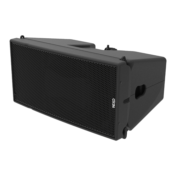
DESCRIPTION DESCRIPTION → GEOM1012-I and GEOM1025-I are a compact high-technology line array, 2 ways passive, with a 10’’ LF and a 1.4’’ HF. You can change the HF horizontal directivity by adding a pair of magnetic flanges. → GEOM1012-I : 12° vertical dispersion →... -
Page 5: Preset Geom10
PRESET GEOM10 PRESET GEOM10 Please consult nexo-sa.com for NEXO TD Controllers firmware information. For the GEOM1012 or GEOM1025, with or without directivity flanges, the following setups are available: o Setup for one stand-alone box, with high-pass at 63, 75, 85, 95 or 120 Hz. - Page 6 PRESET GEOM10 o Possibilities to use 2-3Box setup in stack configuration using MSUB15 in OMNI or CARDIO mode with 1 Back and 2 front and 3 GEOM10 on top of them, application venue up to 15 meters, default cross over 85 Hz but small overlap could have impact if needed, for example (MSUB15 120 Hz and GEOM10 75 Hz).
- Page 7 PRESET GEOM10 Boxes o For long throw flying application used in GEOM10 at 63 Hz without Sub and GEOM10 at 85 Hz with flying MSUB15 in cardio mode at 95 Hz. o For long throw stacking application on floor or on MSUB15, up to 6 boxes used at 63 Hz without Sub and 85 Hz with MSUB15 at 85 Hz.
- Page 8 PRESET GEOM10 7-12 Boxes o For very long throw application used with Sub either ground stack or flying, recommended MSUB15 cardioid mode, cross over MSUB15 95 Hz and 12 GEOM10 cross over 75 Hz for maximum impact. Don’t forget to put HF Waveguide either to the exterior or the interior of the venue.
- Page 9 PRESET GEOM10 GEOM10 MON and MSUB15 MON o Minimum phase setup not compatible with others. o Used for high power stage Monitor, DJ Monitor, Drum Fill, Stack side. o Always use same cross over between GEOM10 and MSUB15, no overlap possible without doing phase adjustment by yourself.
-
Page 10: Geom10 Rigging
GEOM10 RIGGING GEOM10 RIGGING Assembly Front Positioning 2x GEOM10-I.. Connect both cabinets by inserting the axis through front holes and secure axis with brake nuts. Back Adjust the appropriate inter-angle value with the Linkbar and secure with the provided screws. Screws: 1shouder screw (D8x20), 2 washers (M8), 1 brake nut (M6). -
Page 11: Geom10 - Accessories
All GEOM10 accessories are specifically rated in agreement with structural computations. Never use other accessories – including push-pins – when assembling GEOM6 cabinets than the ones provided by NEXO: NEXO will decline responsibility over the entire GEOM10 accessory range if any component is purchased from different supplier. - Page 12 GEOM10 – ACCESSORIES VNT-GSTKM10M12S VNT-GSTKM10M12L Stacking accessories for GEOM10/GEOM12 on VNI/VNT-BUMPM10 Refer to the Product Data Sheet VNT-MNSTKM10 Max 3 GEOM10. Use for stack on MSUB15. Refer to the Product Data Sheet GMT-LBUMP10 Max 12 GEOM10. Usable with GMT-EXBARM10L for 1 rigging point.
- Page 13 GEOM10 – ACCESSORIES VNT-TCBRK3551 Truss Clamp Rotatif Place VNT-TCBRK3551 on GMT-LBUMPM10, GMT-LBUMPM10 or VNT-EXBARM10 at the desired hole. Refer to the Product Data Sheet VNI-LNKM61018 Adapter for GEOM10-I below MSUB18-I. Max 6 GEOM10. Refer to the Product Data Sheet GMT-FLGM10 Pair of flanges for 120°horizontal directivity.
-
Page 14: Array Eq
ARRAY EQ ARRAY EQ The ArrayEQ allows to adjust the system frequency response in its lower range (see curves below, with different ArrayEq values): → GEOM10 → GEOM10 STACK MON Page 14 / 20 GEOM10-I... -
Page 15: Maintenance
MAINTENANCE MAINTENANCE Front panel disassembly Remove the 4 screws (Tx25) to remove the grille. Remove the front panel (8 screws Tx25) Tightening torque: 3.5 Nm To remove the 10’’ driver, remove the 4 screws (Tx25). To remove the HF Driver, unscrew the 4 nuts, and remove it from the wave guide. - Page 16 HF Diaphragm 10’’ Driver (with screws) 05HPB10N 05HPB10NR/K Recone Kit HPB10N (with screws) 05GEOM10UA-I Complete grille Installation Black 05GEOM10UA-IPW Complete grille Installation White NOTE: Speakers and Grills can be sent back to NEXO for recycling Page 16 / 20 GEOM10-I...
-
Page 17: Technical Specifications
TECHNICAL SPECIFICATIONS TECHNICAL SPECIFICATIONS GEOM10 WITH NEXO ELECTRONICS Model GEOM10 59Hz – 20kHz Frequency range (±6dB) Sensibility (1W / 1m) 100dB SPL Nominal Peak SPL Level (1m) 136dB Peak Operating voltage 30 Vrms (180 Vpeak) 12° pour GEOM1012 Vertical Dispersion 25°... -
Page 18: User Notes
USER NOTES USER NOTES Page 18 / 20 GEOM10-I... - Page 19 USER NOTES GEOM10-I Page 19 / 20...
- Page 20 USER NOTES NEXO S.A. Tel: +33 3 44 99 00 70 Fax: +33 3 44 99 00 30 E-mail: info@nexo.fr Parc d’activité de la Dame Jeanne F-60128 PLAILLY nexo-sa.com Page 20 / 20 GEOM10-I...
Need help?
Do you have a question about the GEOM1012-I and is the answer not in the manual?
Questions and answers