
Related Manuals for Nexo GEO D series


Summary of Contents for Nexo GEO D series
-
Page 1: User Manual
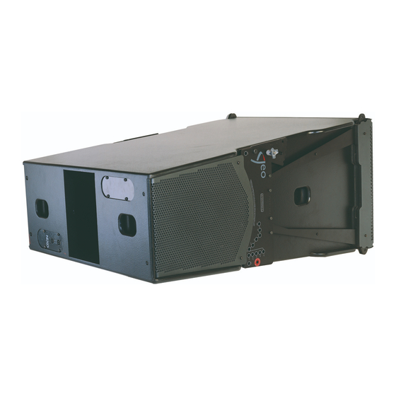
GEO D Series D10 10° Tangent Array Module Geo Sub Directional Sub-bass User Manual GEO D Series User Manual V1.04 Date: 07/06/2007... - Page 2 A comprehensive understanding of GEO theory, tangent arrays, and specific features of the GEO D Series will help you to operate your system at its full potential.
- Page 3 Page 3/93 NTRODUCTION SAFETY ISSUES IMPORTANT NOTICE CONCERNING HIGH SOUND PRESSURE LEVELS Exposure to extremely high noise levels may cause a permanent hearing loss. Individuals vary considerably in susceptibility to noise-induced hearing loss, but nearly everyone will lose some hearing if exposed to sufficiently intense noise for a sufficient time.
-
Page 4: Table Of Contents
GEO SUB Cluster Flying Setup (2 motors required)..........56 Fixed installations ....................63 Testing and Maintenance of the system ..............64 NEXO NX242 Digital Controller for GEO D and GEO SUB.........65 NX242 Proprietary Functions...................65 Cardioid LF and VLF....................67 GEO D NX242 Setups description................67... - Page 5 GEO D cluster to amplifiers and NX242 (Mono active mode)........86 10.3 GEO SUB - GEO D cluster to amplifiers and NX242 (GeoD in Passive Mode)..87 GEO D Series Parts & Accessories List..............88 11.1 Array Modules & Control Electronics List ..............88 11.2...
-
Page 6: Introduction
Page 6/93 NTRODUCTION NTRODUCTION Thank you for selecting a NEXO GEO D Series Tangent Array System. This manual is intended to provide you with necessary and useful information about your GEO System, which includes the following products: • D10 is a 10° Tangent Array Module. It comprises 2x8”... - Page 7 GEOSoft2 Array Design Software simplifies the design and implementation of vertical tangent GEO arrays. Please consult the NEXO web site (www.NEXO.fr or www.NEXO-sa.com) for the latest software releases. Please devote your time and attention to reading this manual. A comprehensive understanding of GEO theory, tangent arrays, and specific features of GEO D10 and GEO SUB and will help you to operate your system at its full potential.
-
Page 8: Geo D General Set-Up Instructions
IF YOUR GEO D’s ARE WITHIN THESE NUMBERS, PLEASE CONTACT NEXO OR YOUR LOCAL DISTRIBUTOR SO THAT INSTRUCTIONS AND COMPONENTS ARE SENT TO YOU FOR FILTER MODIFICATION GEO D SERIAL #0100 to #1610 Please contact NEXO or your local distributor so that instructions and components are sent to you for filter modification... - Page 9 GEO D G Page 9/93 ENERAL NSTRUCTIONS GEO D Serial #1611 to above Configuring for Passive Mode (default configuration) • Connector A & B are link together. • Speaker Connector is in the CN1 (passive) connector located on the PCB Connector B Speaker Connector Connector A...
-
Page 10: Amplifier Selection
2.1.4 Cabling NEXO recommends the exclusive use of multi-conductor cables to connect the system: the cable kit is compatible with all the cabinets, and there is no possible confusion between LF, MF and HF sections. Cable choice consists mainly of selecting cables of the correct sectional dimension (size) in relation to the load resistance and the cable length. - Page 11 GEO D10 is rated for very high power handling and has a 16 Ohms nominal impedance per channel (Passive 2 ways or Active 3 ways). These high impedance values allow connection of 3 to 6 cabinets in parallel for each amplifier channel. Nexo recommends amplifiers in agreement with table below: Recommended Channel 1...
- Page 12 Remember that constant sensitivity settings will give a different gain value when the amplifier power is different. NEXO recommends low gain amplifiers: +26dB is recommended, as it is at the same time adequately low and quite common amongst amplifier manufacturers. This gain setting improves signal to noise ratio and allows all preceding electronic equipment, including the NX242 TDcontroller, to operate at optimum level.
- Page 13 For a 6 GEO D10 and 2 GEO SUB cluster, and considering an amplifier model which is capable of delivering 2 x 3300W into 2 Ohms or 2 x 2300W into 4 Ohms, NEXO recommends the following quantities and settings: •...
-
Page 14: Geosoft2
Geosoft2 installation package includes all GEO User Manuals, Structural Analysis Reports and Certificates PDF files (which can be found in the last section of User Manuals). Geosoft2 is a freeware downloadable on www.nexo-sa.com. Please check our website periodically for upgrades. -
Page 15: Configurable Directivity Device
TORX (head 25) screws per flange on each side of the GEO Waveguide (drawings below); • install the 120° flanges with the six TORX screws • re-install the grid, being carefull that the NEXO logo must be on the GEO Waveguide side. REMOVING THE GRILL REMOVING THE FLANGES... -
Page 16: When & Where To Use Configurable Directivity Flanges
Page 16/93 ONFIGURABLE IRECTIVITY EVICE 4.2 When & where to use Configurable Directivity flanges The diagrams show audience area coverage for a stereo system. While the GEO cluster will deliver even SPL from the front to the rear of this audience area, there are “holes” near the front in the centre and at the outside edges. -
Page 17: Geo Drigging Procedure
Please read it carefully. However, user must always apply his or her knowledge, experience and common sense. If in any doubt, seek advice from your supplier or NEXO agent. This manual offers guidance only for GEO D / GEO SUB loudspeaker systems. References in this manual to other rigging equipment such as motor hoists, steels, shackles etc. - Page 18 • The GEO D / GEO SUB Rigging System requires regular inspection and testing by a competent test centre. NEXO recommend that the system is load tested and certified annually or more frequently if local regulations require. •...
- Page 19 RIGGING PROCEDURE 5.1.3 Contacts Correct training is fundamental to safe practise when working with loudspeakers flying systems. NEXO recommend that users contact local industry associations for information on specialist course. Information for International training agencies can be obtained by contacting either:...
-
Page 20: General Description
5.2 General Description 5.2.1 GEO D10 and GEO SUB Each GEO D and GEO SUB Array Module includes an individual rigging system, which is mounted at the NEXO factory. GEOD10 ARRAY MODULE GEOS SUB ARRAY MODULE GEO D10 and GEO SUB angle sequences are identical and follow logarithmic scales. Angle setting values are: •... - Page 21 Never use other accessories – including push-pins - when assembling GEO D / GEO SUB clusters than the ones provided by NEXO: NEXO will decline responsability over the entire GEOD / GEO SUB rigging system if any component is purchased from different...
- Page 22 Page 22/93 GEO D RIGGING PROCEDURE 5.2.3 Configurations and operating mode General Principle GEO D10 / GEO SUB rigging system operates in compression mode: pull-back force applied between the extreme bottom cabinet and the top bumper set angles between cabinets. When the array is lifted into position all cabinets are at 0°...
- Page 23 GEO D Page 23/93 RIGGING PROCEDURE Described Cases Sections below describe GEO D10 and GEO SUB clusters rigging procedures for the following cases: GEO-BRIDLE GEOD-ORP GEOD-EXBAR4 GEOD-BUMPER GEOD-EXBAR1 Section 5.3 GEOD Ground Stacked Section 5.4 GEO D Cluster One Rigging Point GEOD-BUMPER GEOD-BUPDP LEVA750...
- Page 24 Page 24/93 GEO D RIGGING PROCEDURE GEOD-EXBAR4 GEOD-EXBAR4 GEOD-BUMPER GEOD-EXBAR2 GEOD-BUMPER GEOD-EXBAR2 Section 5.6 Combined GEO D – GEO SUB Cluster Two Rigging Points Section 5.7 GEO SUB Cluster Two Rigging Points LEVA750 LEVA1500 GEOD-BTBUMPER GEOD-EXBAR3 GEOD-BUMPER...
-
Page 25: Geo D - Geo Sub Ground Stacked
GEO D Page 25/93 RIGGING PROCEDURE 5.3 GEO D – GEO SUB Ground Stacked Stacking a GEO D10 cluster requires the following accessories: • 1 x GEO D Main Bumper (GEOD-BUMPER) • 1 x GEO D Bumper Stands kit (GEOD-BUDP) •... - Page 26 IMPORTANT GEO D10 can be stacked “Left” or “Right” : - “Left” means Nexo logo on front grid is left as seen from front; - “Right” means Nexo logo on front grid is right as seen from front. GEO D10 can be connected to bumper “Left” or “Right” by simply flipping the cabinets...
- Page 27 GEO D Page 27/93 RIGGING PROCEDURE BUMPER TO FIRST GEOD ASSEMBLY ‘’LEFT’’ CONFIGURATION ’’RIGHT’’ CONFIGURATION 5.3.4 First to second GEO D 10 FIRST TO SECOND GEO D10...
- Page 28 4 push-pins (BLGEOD, 10mm diameter x 20 mm length) connect first to second GEO D10, 2 additional push pins-are required for angle adjustment. • Lift and position the next GEO D10 above the assembly, with NEXO logo on the same side than the lower cabinet. •...
- Page 29 GEO D Page 29/93 RIGGING PROCEDURE 5.3.5 Subsequent GEO D10’s • Repeat the above section steps, until all GEO D10’s are in place. IMPORTANT DO NOT attempt to make any changes to the angle adjustments without releasing weight on the linking bars. 5.3.6 Ground Stacking GEO SUB with Geo D10’s Proceed exactly as above, bottom cabinet must always be a GEO SUB.
-
Page 30: Geo D Cluster Flying Setup (1 Motor)
Page 30/93 GEO D RIGGING PROCEDURE 5.4 GEO D Cluster Flying Setup (1 motor) Flying a GEO D10 cluster from 1 motor requires the following accessories: • 1 x Motor properly rated • 1 x Geo-Bridle (GEO-BRIDLE) • 1 x GEO D Main Bumper (GEOD-BUMPER) •... - Page 31 GEO D Page 31/93 RIGGING PROCEDURE • Connect the Short Extension Bar EX1 to the Main Bumper through the Link Points the with the two axes using corresponding holes (see drawing below), and ensure that these axes are properly locked with supplied “R” clips; LINKING GEOD BUMPER AND EXTENSION BAR EXBAR1 •...
- Page 32 IMPORTANT GEO D10 can be flown “Left” or “Right” : - “Left” means Nexo logo on front grid is left as seen from front; - “Right” means Nexo logo on front grid is right as seen from front. GEO D10 can be connected to bumper “Left” or “Right” by simply flipping the cabinets...
- Page 33 GEO D Page 33/93 RIGGING PROCEDURE FIRST GEO D10 TO BUMPER ASSEMBLY “RIGHT“ CONFIGURATION “LEFT“ CONFIGURATION 5.4.4 First to second GEO D 10 FIRST TO SECOND GEO D10...
- Page 34 • Lift bumper and top GEO D10 assembly, and position the next GEO D10 below the assembly, with NEXO logo on the same side than the upper cabinet. • Lower bumper and top GEO D10 assembly carefully until the first and second GEO D10 side rigging plates locate.
- Page 35 In case of “Left” configuration, make sure that the bottom link bars cannot hurt anyone going below the cluster. If any doubt, NEXO strongly recommends removing them (screws can be replaced by 10mm x 20mm push-pins to facilitate such change).
- Page 36 Page 36/93 GEO D RIGGING PROCEDURE IMPORTANT DO NOT attempt to make any changes to the angle adjustements when the compression pull-up force is applied. 5.4.7 Positioning the cluster • Adjust the bumper angle as determined in GeoSoft2 by rotating the lever from the bottom of the cluster ;...
- Page 37 GEO D Page 37/93 RIGGING PROCEDURE 5.4.8 De-rigging and loading out Taking the system down is just a case of doing the reverse procedure to flying the array. However, there are some important factors to consider. • Lower the array until the bottom cabinet is just off the floor; •...
- Page 38 Page 38/93 GEO D RIGGING PROCEDURE 5.4.9 Rigging and De-rigging with GEOD Dolly Storage Tray IMPORTANT GEOD Dolly Storage Tray are designed for 3 or 4 GEO D’s + bumper or case ; GEOSUB Dolly Storage Tray is designed for up to 2 GEO SUB’s + bumper or case. Never exceed these quantities.
-
Page 39: Geo D Cluster Flying Setup (2 Motors)
GEO D Page 39/93 RIGGING PROCEDURE 5.5 GEO D Cluster Flying Setup (2 motors) Flying a GEO D10 cluster from 2 motors requires the following accessories: • 2 x Motors properly rated • 1 x GEO D Main Bumper (GEOD-BUMPER) •... - Page 40 IMPORTANT GEO D10 can be flown “Left” or “Right” : - “Left” means Nexo logo on front grid is left as seen from front; - “Right” means Nexo logo on front grid is right as seen from front. GEO D10 can be connected to bumper “Left” or “Right” by simply flipping the cabinets...
- Page 41 GEO D Page 41/93 RIGGING PROCEDURE • Position the bumper on the first GEO D10 by lifting or lowering bumper assembly with motor hoists; • Link the GEO D10 to the bumper assembly using the four 10mm x 20mm push-pins; front bumper connects at GEO D10 front articulation point, rear bumper connects at “LIFT”...
- Page 42 • Lift bumper and top GEO D10 assembly, and position the next GEO D10 below the assembly, with NEXO logo on the same side than the upper cabinet. • Lower bumper and top GEO D10 assembly carefully until the first and second GEO D10 side rigging plates locate.
- Page 43 In case of “Left” configuration, make sure that the bottom link bars cannot hurt anyone going below the cluster. If any doubt, NEXO strongly recommends removing them (screws can be replaced by 10mm x 20mm push-pins to facilitate such change).
- Page 44 Page 44/93 GEO D RIGGING PROCEDURE IMPORTANT DO NOT attempt to force on LEVA750 or LEVA1500 lever once you feel it resisting strongly to rotation; you might damage GEO D flying system by doing so. IMPORTANT DO NOT attempt to make any changes to the angle adjustements when the compression pull-up force is applied.
- Page 45 GEO D Page 45/93 RIGGING PROCEDURE 5.5.7 De-rigging and loading out Taking the system down is just a case of doing the reverse procedure to flying the array. However, there are some important factors to consider. • Lower the array running the two motor hoists simultaneously until the bottom cabinet is just off the floor, main bumper being horizontal.
- Page 46 Page 46/93 GEO D RIGGING PROCEDURE 5.5.8 Rigging and De-rigging with GEOD Dolly Storage Tray IMPORTANT GEOD Dolly Storage Tray are designed for 3 or 4 GEO D’s + bumper or case ; GEOSUB Dolly Storage Tray is designed for up to 2 GEO SUB’s + bumper or case. Never exceed these quantities.
-
Page 47: Geo Sub - Geo D Combined Cluster Flying Setup (2 Motors Required)
GEO D Page 47/93 RIGGING PROCEDURE GEO SUB – GEO D Combined Cluster Flying Setup (2 motors required) Flying a GEO SUB – GEO D combined cluster is very similar to what has been described in the above section, except a long Extension Bar EX2 (instead of EX1) is required to extend top compression point because of GEO SUB depth. - Page 48 GEO D10 and GEO SUB can be flown “Left” or “Right” : - “Left” means Nexo logo on front grid is left as seen from front; - “Right” means Nexo logo on front grid is right as seen from front.
- Page 49 GEO D Page 49/93 RIGGING PROCEDURE 4 push-pins (BLGEOD, 10mm diameter x 20 mm length) connect the top GEO SUB to the bumper. • Position the bumper on the first GEO SUB by lifting or lowering bumper assembly with motor hoists;...
- Page 50 • Lift bumper and top GEO SUB assembly, and position the next GEO SUB below the assembly, with NEXO logo on the same side than the upper cabinet. • Lower bumper and top GEO SUB assembly carefully until the first and second GEO SUB side rigging plates locate.
- Page 51 • Lift bumper and top GEO SUB assembly, and position the next GEO SUB below the assembly, with NEXO logo on the same side than the upper cabinet. • Lower bumper and top GEO SUB assembly carefully until the GEO SUB and GEO D10 side rigging plates locate.
- Page 52 4 push-pins (BLGEOD, 10mm diameter x 20 mm length) connect first to second GEO D10, 2 additional push pins-are required for angle adjustment. • Lift cluster, and position the next GEO D10 below the assembly, with NEXO logo on the same side than the upper cabinet. •...
- Page 53 In case of “Left” configuration, make sure that the bottom link bars cannot hurt anyone going below the cluster. If any doubt, NEXO strongly recommends removing them (screws can be replaced by 10mm x 20mm push-pins to facilitate such change).
- Page 54 Page 54/93 GEO D RIGGING PROCEDURE IMPORTANT DO NOT attempt to force on LEVA750 or LEVA1500 lever once you feel it resisting strongly to rotation; you might damage GEO D flying system by doing so IMPORTANT DO NOT attempt to make any changes to the angle adjustements when the compression pull-up force is applied.
- Page 55 GEO D Page 55/93 RIGGING PROCEDURE 5.6.9 De-rigging and loading out Taking the system down is just a case of doing the reverse procedure to flying the array. However, there are some important factors to consider. • Lower the array running the two motor hoists simultaneously until the bottom cabinet is just off the floor, main bumper being horizontal.
-
Page 56: Geo Sub Cluster Flying Setup (2 Motors Required)
Page 56/93 GEO D RIGGING PROCEDURE 5.7 GEO SUB Cluster Flying Setup (2 motors required) Flying a GEO SUB cluster is very similar to what has been described in the above sections, except: • Long Extension Bar EX2 (instead of EX1) has to be used to extend compression point because of GEO SUB depth;... - Page 57 IMPORTANT GEO SUB can be flown “Left” or “Right” : - “Left” means Nexo logo on front grid is left as seen from front; - “Right” means Nexo logo on front grid is right as seen from front. GEO SUB can be connected to bumper “Left” or “Right” by simply flipping the cabinets...
- Page 58 Page 58/93 GEO D RIGGING PROCEDURE ‘’LEFT’’ CONFIGURATION ’’RIGHT’’ CONFIGURATION 4 push-pins (BLGEOD, 10mm diameter x 20 mm length) connect the top GEO SUB to the bumper. • Position the bumper on the first GEO SUB by lifting or lowering bumper assembly with motor hoists;...
- Page 59 • Lift bumper and top GEO SUB assembly, and position the next GEO SUB below the assembly, with NEXO logo on the same side than the upper cabinet. • Lower bumper and top GEO SUB assembly carefully until the first and second GEO SUB side rigging plates locate.
- Page 60 Page 60/93 GEO D RIGGING PROCEDURE « SAFETY PIN MUST BE FITTED » HOLE IMPORTANT Ensure angle settings are identical on both sides of the cabinet. 5.7.4 Subsequent GEO SUB’s • Repeat the above section steps, until all GEO SUB’s are in place. As the assembly is lifted, angles between GEO SUB’s cabinets will remain at 0°...
- Page 61 GEO D Page 61/93 RIGGING PROCEDURE 5.7.5 Applying compression with the Chain Lever Hoist • Once the GEO SUB assembly is completed, connect the second GEO D Main Bumper below the last GEO SUB with the 10mm x 20mm push-pins inserted in the “FIX” bottom hole (see drawings below).
- Page 62 Page 62/93 GEO D RIGGING PROCEDURE • Rotate the fingerwheel clockwise until the chain is taught; • Make a final check that the Chain Lever Hoist is correctly installed; • Rotate the lever to apply the pull-up force to the bottom of the array; notice that, as the chain gets shorter, the cabinets in the array close together to the angles set by the angle adjustments push- pins;...
-
Page 63: Fixed Installations
GEO D Page 63/93 RIGGING PROCEDURE 5.7.7 De-rigging and loading out Taking the system down is just a case of doing the reverse procedure to flying the array. However, there are some important factors to consider. • Lower the array running the two motor hoists simultaneously until the bottom cabinet is just off the floor, main bumper being horizontal. -
Page 64: Testing And Maintenance Of The System
• place bolts and nuts according to drawing below • re-install the grid, being carefull that the NEXO logo must be on the GEO Waveguide side. 5.9 Testing and Maintenance of the system • General: Geo is a precision piece of equipment and requires regular attention to maintenance in order to give long and reliable service. -
Page 65: Nexo Nx242 Digital Controller For Geo Dand Geo Sub
6.1.1 Upgradable Firmware NEXO releases regular firmware updates. Each new release is the result of our ongoing R&D program combined with user feedback from the field. New firmware releases can include new setups for different combinations of NEXO full range loudspeakers and subwoofers, improvements to existing setups, and new software functions. - Page 66 Page 66/93 NEXO NX242 D GEO D GEO SUB IGITAL ONTROLLER FOR 6.1.3 Protection VCAs and VCEQs Each channel has its own simulation and protection process. Each audio channel contains a combination of controlled gain stages (let's call them VCAs as in analogue circuitry). These VCAs are...
-
Page 67: Cardioid Lf And Vlf
NEXO NX242 D GEO D GEO SUB Page 67/93 IGITAL ONTROLLER FOR The Physio control voltage acts independently on the VCA with its operation threshold slightly (3 dB) above that of the temperature limiter and a low compression ratio; its optimised attack time constant allows it to start operating without any subjectively unpleasant transient effects. -
Page 68: Trouble Shooting
The NX242 has been designed to be user-friendly. However with highly technical systems such as GEO D & GEO SUB, incorrect adjustment of the NX242 can lower the quality & safety of your system. Listed below are the most common errors encountered by NEXO Technical Support. 6.4.1 Operation of Multiple TDcontrollers Typically, GEO D / GEO SUB systems require multiple NX242’s per side. - Page 69 Using the wrong NX242 setups for a given cabinet Each NX242 setup is tailored for a certain NEXO loudspeaker. Using the wrong setup will create safety and quality problems. Always check that every cabinet in your system is being driven by the correct NX242 setup.
-
Page 70: System Alignment Guidelines
IMPORTANT Geosoft2 is a freeware downloadable on www.nexo-sa.com. Please check our website periodically for upgrades. Never install a GEO D / GEO SUB cluster without checking its acoustical performances and mechanical safety in Geosoft2 prior to installation. -
Page 71: Flown Or Stacked Combined Geo Sub's And Geo D's Clusters
& safety of the system (mostly time alignment). At NEXO, great care is taken to design optimum phase alignment from one octave above to one octave below the crossover frequency point. By doing so, drivers are working perfectly together and providing the best efficiency possible. -
Page 72: Recommended Installation Tools And Equipment
Computer – Laptop or Desktop PC running Windows 2000 or XP with the current version of NEXO GeoSoft2 installed. It is not possible to configure a Geo tangent array properly without using GeoSoft2. Note that, when GeoSoft2 designs are prepared prior to arrival at the venue, it is often necessary to modify or update the design to accommodate special circumstances. -
Page 73: Geo D - Geo Sub Array System Check List
GEO D – GEO SUB A Page 73/93 RRAY YSTEM HECK GEO D – GEO SUB A RRAY YSTEM HECK It is essential to execute all these check steps prior to perform a sound check on the “front end” to the system. -
Page 74: Final Pre-Sound Check Check
Page 74/93 GEO D – GEO SUB A RRAY YSTEM HECK only are on. When listening from the front, you should hear a strong increase in the LF range when connecting the rear drivers. • To check that all front elements have the proper amplitude and phase, you should listen to the upper boxes at a close distance (<1 meter). -
Page 75: Technical Specifications
SYSTEM OPERATION Electronic controller The NX242 Digital TDcontroller (with NX-Tension Card) presets are precisely matched to the GEO D Series cabinets and include sophisticated protection systems as well as advanced cardioid directivity DSP algorithms. Using GEO D Series cabinets without a properly connected NX242 & NX-Tension Card will result in poor sound quality and can damage components. - Page 76 Page 76/93 ECHNICAL PECIFICATIONS 9.1.2 GEO D10 Dimensions [29 1/2"] 744 mm 9.1.3 GEO D10 Diagrams [dB] Level, Sound pressure [ohm] Amplitude log, Impedance Frequency [Hz] Frequency [Hz] FC: 1 x Geo D10 Overlap, 1/ 3oct smoot hing, values scaled FC: 1 x Geo D10 Crossover, 1/ 3oct smoot hing, values scaled FC: Geo D10 impedance f ront speakers FC: Geo D10 impedance back speakers...
-
Page 77: Geo Sub Directional Sub-Bass
Please refer to the user manual before any operation. As part of a policy of continual improvement, NEXO reserves the right to change specifications without notice. Response curves and data: anechoic far field above 400 Hz, half-space anechoic below 400 Hz. - Page 78 Page 78/93 ECHNICAL PECIFICATIONS 9.2.2 GEO SUB dimensions [29 1/2"] 744 mm 9.2.3 GEO SUB diagrams [dB] Level, Sound pressure [ohm] Amplitude log, Impedance Frequency [Hz] Frequency [Hz] F: Geo SUB Crossover, 1/ 3oct log smoot hing, values scaled F: Geo SUB Overlap, 1/ 3oct log smoot hing, values scaled FC: Geo SUB f ront impedance FC: Geo SUB rear Impedance...
-
Page 79: Geo D / Geo Sub Rigging System
Page 79/93 ECHNICAL PECIFICATIONS 9.3 GEO D / GEO SUB Rigging system 9.3.1 GEO D / GEO SUB Bumper [28"] 715 mm WEIGHT : 45 KG / 99.2 LBS 9.3.2 GEO D Short Extension Bar EX1 [2 1/2"] 65 mm WEIGHT : 5.3 KG / 11.7 LBS... - Page 80 Page 80/93 ECHNICAL PECIFICATIONS 9.3.3 9.3.4 GEO D – ORP (Compression Wheel for EX1 Only) 95 mm 25.5 mm 51 mm WEIGHT: 0.250KG / 0.55 LBS 9.3.5 GEO BRIDLE WEIGHT: 3 KG / 6.6 LBS 9.3.6 GEO D Long Extension Bar EX2 [2 1/2"] 65 mm WEIGHT: 13.1 KG / 28.9 LBS...
- Page 81 Page 81/93 ECHNICAL PECIFICATIONS 9.3.7 GEO SUB Bottom Extension Bar EX3 [2 1/2"] 65 mm WEIGHT: 16.1 KG / 35.5 LBS 9.3.8 GEO D Front Extension Bar EX4 [2 1/2"] 65 mm WEIGHT: 6.9 KG / 15.2 LBS 9.3.9 GEO D Bottom Bumper [28 1/2"] 722 mm WEIGHT: 10.4 KG / 22.9 LBS...
- Page 82 Page 82/93 ECHNICAL PECIFICATIONS 9.3.10 GEO D Chain Lever Hoists MAX LOAD 750 KG / 1650 LBS MAX LOAD 1500 KG / 3300 LBS WEIGHT: 10.3 KG / 22.7 LBS WEIGHT: 23.7 KG / 52.2 LBS CHAIN LENGTH: 6 M / 16.7 FT CHAIN LENGTH: 9M / 29.5 FT 9.3.11 GEO D / GEO SUB Push-Pins 20 mm...
-
Page 83: Nx242 Tdcontroller With Nx-Tension Card
Individual Mute/Solo buttons and red LED for each channel Amp. Sense & Peak (green & red) LED’s for each channel FLASH EPROM Software updates/upgrades, new system setups, available on www.nexo-sa.com Rear Panel RS232 connector for serial com 2 x RJ45 connectors with NXTension ES4 Card 1 RJ45 + 2 RJ11 with NXTension CAI Card Dimensions &... -
Page 84: Block Diagram
Page 84/93 ECHNICAL PECIFICATIONS 9.4.3 Block Diagram... -
Page 85: Connection Diagrams
Page 85/93 ONNECTION DIAGRAMS 10 C ONNECTION DIAGRAMS 10.1 GEO D cluster to amplifiers and NX242 (Stereo passive mode) FROM AMPLIFIERS TO AMPLIFIERS HF + HF + + 4 - + 3 - + 2 - + 1 - RIGHT LEFT REAR REAR... -
Page 86: Geo D Cluster To Amplifiers And Nx242 (Mono Active Mode)
Page 86/93 ONNECTION DIAGRAMS 10.2 GEO D cluster to amplifiers and NX242 (Mono active mode) FROM AMPLIFIERS TO AMPLIFIERS N.C. HF LF/MF N.C. IN + 3 - + 2 - + 1 - FRONT REAR 1 (-) / 2 (+) REAR LF 3 (-) / 4(+) FRONT LF/MF 5 (-) / 6 (+) HF EP6 F... -
Page 87: Geo Sub - Geo D Cluster To Amplifiers And Nx242 (Geod In Passive Mode)
Page 87/93 ONNECTION DIAGRAMS 10.3 GEO SUB - GEO D cluster to amplifiers and NX242 (GeoD in Passive Mode) FROM AMPLIFIERS TO AMPLIFIERS GEO D HF + + 4 - + 3- + 2 - + 1 - REAR LF/MF FRONT REAR FRONT... -
Page 88: Geo D Series Parts & Accessories List
Page 88/93 GEO D S & A ERIES ARTS CCESSORIES 11 GEO D S & A ERIES ARTS CCESSORIES 11.1 Array Modules & Control Electronics List MODEL DRAWING DESCRIPTION GEO D10 GEO D 10° Cardioid Main Module GEO SUB GEO SUB 10° Cardiod Sub-Bass Module ANX 242 Digital TDcontroller for PS, Alpha and Geo series NX-ES4... - Page 89 GEO D S & A Page 89/93 ERIES ARTS CCESSORIES MODEL DRAWING DESCRIPTION GEOD-EXBAR 2 Geo D Extension Bar for GEO D10 / GEOSUB Cluster GEOD-EXBAR 3 Geo D Bottom Extension Bar for GEOSUB Cluster Geo D Front Extension Bar for GEO D10 / GEO SUB GEOD-EXBAR4 Clusters LEVA1500...
- Page 90 Page 90/93 GEO D S & A ERIES ARTS CCESSORIES GEOSUB-DOLLY 2 x GEOSUB + 1 x GEOD-BUMPER Dolly...
- Page 91 GEO D S & A Page 91/93 ERIES ARTS CCESSORIES MODEL DRAWING DESCRIPTION Nylon Cover for • 3 GEO D10 GEOD-DCOVER • 1 GeoD-BKM or 1GEOD-BUMPER • 1 GEOD-DOLLY Nylon Cover for • 4 GEO D10 GEOD-DCOVER4 • 1 GeoD-BKM or 1GEOD-BUMPER •...
-
Page 92: User Notes
Page 92/93 USER NOTES 12 USER NOTES... - Page 93 USER NOTES Page 93/93 France Nexo S.A. 154 allée des Erables ZAC des PARIS NORD II B.P. 50107 F-95950 Roissy CDG Cedex Tel: +33 1 48 63 19 14 Fax: +33 1 48 63 24 61 E-mail: info@nexo.fr www.nexo-sa.com...
Need help?
Do you have a question about the GEO D series and is the answer not in the manual?
Questions and answers