Table of Contents
Advertisement
Quick Links
Advertisement
Table of Contents

Related Manuals for Nexo GEOM1210-I


Summary of Contents for Nexo GEOM1210-I
- Page 1 DP2818-01-DI GEO M12 Series GEOM1210-I – GEOM1220-I User manual...
-
Page 2: Table Of Contents
Is in conformity with the provisions of the following directive 2014/35/UE (Low Voltage Directive) including all applicable amendments: Applied rules and standards: EN 13155, EN 62368 Plailly, January, 2019 Joseph CARCOPINO, R&D Director Page 2 / 20 GEOM1210-I - GEOM1220-I... -
Page 3: Warnings
If the system seems to be malfunctioning or damaged, stop using it at once and have it repaired by a NEXO qualified technician. Do not expose the system directly to the sun or to the rain, do not immerse it into fluids, do not place objects filled with liquid on the system. -
Page 4: Description
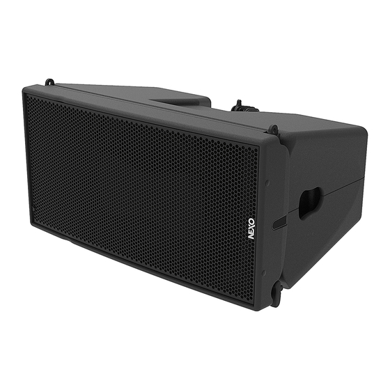
DESCRIPTION GEOM1210-I and GEOM1220-I are a mid-size line array, 2 ways active/passive, with a 12’’ LF and a 1.4’’ HF. You can change the HF horizontal directivity from 80° to 120° by adding a pair of magnetic flanges. -
Page 5: Preset Geom12
PRESET GEOM12 PRESET GEOM12 Please consult nexo-sa.com for NEXO TD Controllers firmware information. For the GEOM1210 or GEOM1220, with or without directivity flanges, the following setups are available: Passive Mode Setup for one stand-alone box, with high-pass at 50, 60, 75, 85, 95 or 120 Hz. - Page 6 Back and 2 Front and 3 GEOM12 on top of them, application venue up to 25 meters, default cross over 85 Hz but small overlap could have impact if needed, for example (MSUB18 120Hz and GEOM12 75 Hz). Page 6 / 20 GEOM1210-I - GEOM1220-I...
- Page 7 MSUB18 in omni mode at 95 Hz. For long throw stacking application on floor or on MSUB18, up to 6 boxes used at 60 Hz without Sub and 85 Hz with MSUB18 at 85 Hz. GEOM1210-I - GEOM1220-I Page 7 / 20...
- Page 8 MSUB18 cardioid mode, cross over MSUB18 95 Hz and 12 GEOM12 cross over 75 Hz for maximum impact. Don’t forget to put HF Waveguide either to the exterior or the interior of the venue. Ground Stack Sub design Page 8 / 20 GEOM1210-I - GEOM1220-I...
-
Page 9: Geom12 Rigging
Back Adjust the appropriate inter-angle value with the Linkbar and secure with the provided screws. Screws: 1 shoulder screw (D10x20), 2 washers (M10), 1 brake nut (M8). GEOM1210-I - GEOM1220-I Page 9 / 20... -
Page 10: Geom12 - Accessories
All GEOM12 accessories are specifically rated in agreement with structural computations. Never use other accessories – including push-pins – when assembling GEOM12 cabinets than the ones provided by NEXO: NEXO will decline responsibility over the entire GEOM12 accessory range if any component is purchased from different supplier. - Page 11 Rated for a maximum of 3 GEOM12 on the top of MSUB18. GMT-LBUMPM12 Rated for a maximum of 12 GEOM12. Usable with GMT-EXBARM12L for a one rigging point. GMT-EXBARM12L GMT-FLGM12 Pair of flanges for 120°horizontal directivity. No tools, magnetic clamp. GEOM1210-I - GEOM1220-I Page 11 / 20...
-
Page 12: Array Eq
ARRAY EQ ARRAY EQ The ArrayEQ allows to adjust the system frequency response in its lower range (see curves below, with different ArrayEq values): Page 12 / 20 GEOM1210-I - GEOM1220-I... -
Page 13: Maintenance
To remove the 12’’ driver, remove the 8 screws (Tx25). To remove the HF Driver, unscrew the 4 nuts, and Pay attention to the 4 spacers below the PMP. remove it from the wave guide. Tightening torque for the 12’’: 3.5 Nm GEOM1210-I - GEOM1220-I Page 13 / 20... - Page 14 Lexan Warning White 05LEXRIG-ANGL1 Lexan Rigging Angles 05LEXRIG-ANGL1-PW Lexan Rigging Angles White 05LEXCNX-M1210-I Lexan CNX GEOM1210-I 05LEXCNX-M1210-IPW Lexan CNX GEOM1210-I White 05LEXCNX-M1220-I Lexan CNX GEOM1220-I 05LEXCNX-M1220-IPW Lexan CNX GEOM1220-I White 05GEOM12UA-I Complete grille Installation Black 05GEOM12UA-IPW Complete grille Installation White...
-
Page 15: Technical Specifications
TECHNICAL SPECIFICATIONS TECHNICAL SPECIFICATIONS GEOM12 WITH NEXO ELECTRONICS Model GEOM12 50Hz – 20kHz Frequency range (±6dB) Sensibility (1W / 1m) 105dB SPL Nominal Peak SPL Level (1m) 140dB Operating voltage 50 Vrms (180 Vpeak) 10° for GEOM1210 Vertical Dispersion 20° for GEOM1220 Horizontal Dispersion 80°... -
Page 16: User Notes
USER NOTES USER NOTES Page 16 / 20 GEOM1210-I - GEOM1220-I... - Page 17 USER NOTES GEOM1210-I - GEOM1220-I Page 17 / 20...
- Page 18 USER NOTES Page 18 / 20 GEOM1210-I - GEOM1220-I...
- Page 19 USER NOTES GEOM1210-I - GEOM1220-I Page 19 / 20...
- Page 20 USER NOTES NEXO S.A. Tel: +33 3 44 99 00 70 Fax: +33 3 44 99 00 30 E-mail: info@nexo.fr Parc d’activité de la Dame Jeanne F-60128 PLAILLY nexo-sa.com Page 20 / 20 GEOM1210-I - GEOM1220-I...
Need help?
Do you have a question about the GEOM1210-I and is the answer not in the manual?
Questions and answers