Table of Contents
Advertisement
Quick Links
Advertisement
Table of Contents

Related Manuals for NXP Semiconductors FRDM-MCXA153


Summary of Contents for NXP Semiconductors FRDM-MCXA153
- Page 1 FRDM-MCXA153 Board User Manual Rev. 1 — 25 January 2024 User manual Document information Information Content Keywords UM12012, FRDM-MCXA153, MCXA1xx, Pmod, mikroBUS, Arduino, MCU-Link Abstract The FRDM-MCXA153 board is a design and evaluation platform based on the NXP MCXA1xx MCU.
-
Page 2: Board Overview
FRDM-MCXA153 Board User Manual 1 Board overview The FRDM-MCXA153 board is a design and evaluation platform based on the NXP MCXA1xx MCU. The MCXA1xx MCU is a low-power microcontroller for industrial and consumer Internet of Things (IoT) applications. It has one Arm Cortex-M33 core running at speeds of up to 96 MHz. It supports industrial communication protocol, brushless direct current (BLDC) motor / permanent magnet synchronous motor (PMSM) control, and integrated sensor interfaces (MIPI-I3C, I2C, and SPI). -
Page 3: Kit Contents
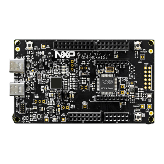
USB 3.0 Type-A to Type-C cable, 1 meter FRDM-MCXA153 Quick Start Guide 1.4 Board pictures Figure 2 shows the top-side view of the FRDM-MCXA153 board with MCXA1xx MCU highlighted. Figure 2. Board top-side view UM12012 All information provided in this document is subject to legal disclaimers. - Page 4 UM12012 NXP Semiconductors FRDM-MCXA153 Board User Manual Figure 3 shows the bottom-side view of the FRDM-MCXA153 board. Figure 3. Board bottom-side view UM12012 All information provided in this document is subject to legal disclaimers. © 2024 NXP B.V. All rights reserved.
-
Page 5: Connectors
Note: External debugger connector (J18), which is shown populated in Figure 4, is not populated on the FRDM-MCXA153 boards shipped to customers. Table 3 describes the connectors available on the FRDM-MCXA153 board. Table 3. FRDM-MCXA153 connectors Part identifier PCB label Connector type... -
Page 6: Jumpers
J25 (DNP) MCU-Link 1x3-pin/position MCU-Link VCOM connector Section 2.4 VCOM connector 1.6 Jumpers Figure 5 shows the FRDM-MCXA153 board jumpers. JP1 (DNP) JP20 JP10 JP19 (DNP) (DNP) Figure 5. Jumpers Table 4 describes the FRDM-MCXA153 board jumpers. Table 4. FRDM-MCXA153 jumpers... - Page 7 UM12012 NXP Semiconductors FRDM-MCXA153 Board User Manual Table 4. FRDM-MCXA153 jumpers ...continued Part identifier Jumper type Description Reference section (after removing resistor R66), it can be used to serve the following two purposes: • To produce the target MCU analog power supply, VDDA_MCU.
-
Page 8: Push Buttons
FRDM- enabled. MCU-Link drives SWD of the target MCU. MCXA153 board schematics. 1.7 Push buttons Figure 6 shows the FRDM-MCXA153 board push buttons. SW1 (Reset) SW3 (Wake-up) SW2 (ISP) Figure 6. Push buttons Table 5 describes the FRDM-MCXA153 board push buttons. -
Page 9: Leds
(SWD) / ISP) (MCU-Link VCOM) (RGB) D4 (Power) Figure 7. LEDs Table 6 describes the FRDM-MCXA153 board LEDs that correspond to the target MCU. The board also has some MCU-Link specific LEDs, which are described in Section 3.8. Table 6. FRDM-MCXA153 LEDs Part identifier... -
Page 10: Functional Description
• Section 2.10 "Arduino socket" 2.1 Power supplies The FRDM-MCXA153 board is powered up using the following primary power supplies: • External 5 V power through USB Type-C connector J8 • External 5 V power through USB Type-C connector J15 •... -
Page 11: Current Measurement
Provides VREFP power to the LPC55S69 MCU (MCU- MCULINK Link) 2.1.1 Current measurement The FRDM-MCXA153 board supports current measurement using an ampere meter (ammeter) on power supplies shown in Table UM12012 All information provided in this document is subject to legal disclaimers. -
Page 12: Clocks
The MCXA1xx MCU has one Universal Serial Bus Full Speed (USBFS) module (USBFS0), which supports only Device mode. The FRDM-MCXA153 board implements support for the USBFS module through a USB Type-C connector, J8. The USB connector works in Device mode. It also flows 5 V power in the board. - Page 13 LPUART2_RXD-MIKROE connector J5 LPUART2 LPUART2_TXD-ARD_D1_TX Arduino socket LPUART2_RXD-ARD_D0_RX connector J1 Figure 8. LPUART diagram Table 10 describes the FRDM-MCXA153 LPUART connections. Table 10. LPUART connections LPUART Peripheral devices module Part identifier Manufacturer and part number Description LPUART0 NXP LPC55S69JEV98 MCU-Link, a 32-bit MCU based on the Arm Cortex- M33 core with speeds of up to 150 MHz.
-
Page 14: Lpspi Interface
Each LPSPI module supports two modes: Master mode (with support for up to four peripheral chip selects) and Slave mode. The FRDM-MCXA153 board supports communication with both the LPSPI modules of the MCXA1xx MCU. Figure 9 shows the FRDM-MCXA153 LPSPI diagram. -
Page 15: Lpi2C Interface
J2 Figure 10. LPI2C diagram Table 12 describes the FRDM-MCXA153 LPI2C devices. The I2C address of each device depends on the plugged-in board/module. UM12012 All information provided in this document is subject to legal disclaimers. © 2024 NXP B.V. All rights reserved. -
Page 16: I3C Sensor
One of the four Arduino socket connectors that allows an I2C connection between the target MCU and the plugged-in Arduino board. 2.7 I3C sensor The FRDM-MCXA153 board provides a digital temperature sensor, which is supported through the Improved Inter-Integrated Circuit (I3C) module (I3C0) of the MCXA1xx MCU. Table 13 describes the I3C sensor. -
Page 17: Mikrobus Socket
A mikroBUS socket is a pair of 1x8 position receptacles (connectors) with a proprietary pin configuration and silkscreen markings. It allows maximum hardware expandability with the least number of pins. The FRDM-MCXA153 board has a mikroBUS socket with two 1x8 position receptacles, J5 and J6. Figure 11 shows the pinouts of the mikroBUS socket connectors. - Page 18 UM12012 NXP Semiconductors FRDM-MCXA153 Board User Manual The two 2x8-position receptacles are placed diagonally opposite to each other. The socket is pin-compatible with an Arduino Uno revision 3 (R3) board. The Arduino socket allows communication with the following modules of the target MCU: •...
-
Page 19: Mcu-Link Ob Debug Probe
MCU-Link Debug Probe Architecture page. The MCU-Link OB on the FRDM-MCXA153 board is factory-programmed with the firmware based on the NXP CMSIS-DAP protocol. The firmware also supports all other features supported in the hardware. A custom version of the J-Link firmware to make MCU-Link OB compatible with J-Link LITE is also available. However, this firmware version supports only limited features, including debug/SWO and VCOM. -
Page 20: Mcu-Link Host Driver And Utility Installation
UM12012 NXP Semiconductors FRDM-MCXA153 Board User Manual Table 16. Supported debug scenarios ...continued Debug scenario Feature support Required jumper/connector settings Use MCU-Link for debugging an SWD: Enabled JP20 is open. external target Populate J18 and connect the external target to it. -
Page 21: Using Mcu-Link With Development Tools
CMSIS-DAP probes or J-Link probes (depending on the firmware image you are using). 3.6 MCU-Link USB connector The FRDM-MCXA153 board has a USB Type-C connector J15, which allows you to connect MCU-Link with your host computer. It can also be used to supply 5 V power to the board. -
Page 22: Vcom Port (Usb To Target Uart Bridge)
MCU while working as a USB-to-UART bridge. In the FRDM-MCXA153 board, MCU-Link is connected to the LPUART0 port of the target MCU. To use MCU- Link as a USB-to-UART bridge, verify the following jumper settings and connect the J15 connector on the board to the USB port of the host computer: •... -
Page 23: Board Errata
UM12012 NXP Semiconductors FRDM-MCXA153 Board User Manual 4 Board errata Not applicable for the current board revision. UM12012 All information provided in this document is subject to legal disclaimers. © 2024 NXP B.V. All rights reserved. User manual Rev. 1 — 25 January 2024... -
Page 24: Related Documentation
FRDM-MCXA153 board. Some of these documents may be available only under a non-disclosure agreement (NDA). To access such a document, contact a local NXP field applications engineer (FAE) or sales representative. -
Page 25: Acronyms
UM12012 NXP Semiconductors FRDM-MCXA153 Board User Manual 6 Acronyms Table 20 lists the acronyms used in this document. Table 20. Acronyms Acronym Description Analog-to-Digital Converter BLDC Brushless direct current Do not populate / do not place Full-speed Inter-Integrated Circuit Improved Inter-Integrated Circuit... -
Page 26: Revision History
UM12012 NXP Semiconductors FRDM-MCXA153 Board User Manual 7 Revision history Table 21 summarizes the revisions to this document. Table 21. Revision history Document ID Release date Description UM12012 v.1 25 January 2024 Initial public release UM12012 All information provided in this document is subject to legal disclaimers. -
Page 27: Legal Information
NXP Semiconductors. In the event that customer uses the product for design-in and use in In no event shall NXP Semiconductors be liable for any indirect, incidental, automotive applications to automotive specifications and standards, punitive, special or consequential damages (including - without limitation - customer (a) shall use the product without NXP Semiconductors’... - Page 28 UM12012 NXP Semiconductors FRDM-MCXA153 Board User Manual AMBA, Arm, Arm7, Arm7TDMI, Arm9, Arm11, Artisan, big.LITTLE, MCX — is a trademark of NXP B.V. Cordio, CoreLink, CoreSight, Cortex, DesignStart, DynamIQ, Jazelle, Keil, Mali, Mbed, Mbed Enabled, NEON, POP, RealView, SecurCore, Socrates, Thumb, TrustZone, ULINK, ULINK2, ULINK-ME, ULINK- PLUS, ULINKpro, μVision, Versatile —...
-
Page 29: Table Of Contents
UM12012 NXP Semiconductors FRDM-MCXA153 Board User Manual Contents Board overview ..........2 Block diagram ............2 Board features ........... 2 Kit contents ............3 Board pictures ........... 3 Connectors ............5 Jumpers ............. 6 Push buttons ............8 LEDs ..............9 Functional description ........10 Power supplies ..........
Need help?
Do you have a question about the FRDM-MCXA153 and is the answer not in the manual?
Questions and answers