Table of Contents
Advertisement
Quick Links
IBS IP 400 ME-ELR R-3A FO
Module Electronics of an Electronic
Reversing-Load Motor Starter With Fiber
Optic Connection
Data Sheet 6550A
Product Description
The reversing-load motor starter with electronic
motor monitoring switches three-phase
asynchronous motors via INTERBUS.
Features
–
INTERBUS protocol (EN 50254)
–
Fiber optic connection
–
Electronic motor monitoring according to
IEC 60947-4:1990 and, if required, via
thermistors
–
Electronic solid-state contact for an external
braking device
–
Hand-held operator panel mode (HHOP)
–
Connection for four digital sensors and two
digital actuators
–
Error acknowledgment locally or via the bus
–
Electrical isolation between bus and I/O
devices
–
Safe isolation between AC supply voltage
and 24 V supply voltage according to
EN 50178:1997
–
LED diagnostic and status indicators
–
Motor current monitoring
–
Motor control via digital inputs
–
Sheet-steel housing with IP 54 protection
6550A
11/2002
Application
Three-phase asynchronous motors
–
200 V AC, minimum, to 440 V AC, maximum
–
Nominal motor current of 0.2 A to 3.6 A
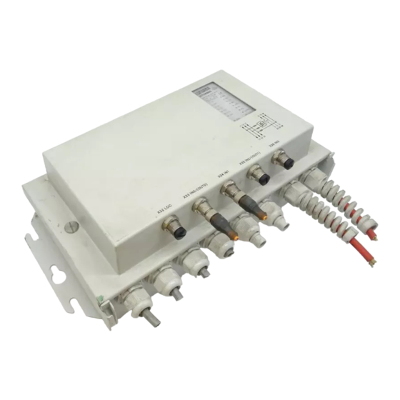
Figure 1
1
Module electronics
2
LED diagnostic and status indicators
3
Cover mounting screw
4
Mounting element
5
Mounting base housing (not supplied as
standard)
6
Sensor inputs/outputs
7
HHOP connection
Module view
1
Advertisement
Table of Contents

Subscribe to Our Youtube Channel
Related Manuals for Phoenix Contact IBS IP 400 ME-ELR R-3A FO


Summary of Contents for Phoenix Contact IBS IP 400 ME-ELR R-3A FO
- Page 1 IBS IP 400 ME-ELR R-3A FO Module Electronics of an Electronic Reversing-Load Motor Starter With Fiber Optic Connection Data Sheet 6550A 11/2002 Product Description Application The reversing-load motor starter with electronic Three-phase asynchronous motors motor monitoring switches three-phase – 200 V AC, minimum, to 440 V AC, maximum asynchronous motors via INTERBUS.
- Page 2 IBS IP 400 ME-ELR R-3A FO This data sheet is only valid in association with the Installation Guidelines IBS IP 400 ELR INST. Explanation of Symbols Used This data sheet contains information that must be noted for your own safety and to avoid damage to equipment.
- Page 3 They can therefore cause Phoenix Contact cannot guarantee the considerable damage to health or equipment, suitability of the procedures described or the e.g., due to the unauthorized removal of circuit suggestions for the relevant application.
-
Page 4: Table Of Contents
IBS IP 400 ME-ELR R-3A FO Table of Contents 1 Correct Usage ......................5 2 General Description ....................6 2.1 Area of Application ..................6 2.2 Properties ....................6 2.3 LED Diagnostic and Status Indicators ............7 2.4 Function Groups of the Module ..............9 2.5 Cable Arrangement .................. -
Page 5: Correct Usage
Explanation of Symbols Used Correct Usage The module is only to be used as specified in Information about assembly and the catalog and this data sheet. Phoenix installation of the module can be Contact accepts no liability if the device is used found in the Installation Guidelines for anything other than its designated use. -
Page 6: General Description
IBS IP 400 ME-ELR R-3A FO General Description 2.1 Area of Application The reversing-load motor starter enables the connection, disconnection, and reversing-load operation of a three-phase asynchronous motor in production and conveying systems that are networked with INTERBUS. 2.2 Properties... -
Page 7: Led Diagnostic And Status Indicators
Explanation of Symbols Used 2.3 LED Diagnostic and Status Indicators Figure 2 LED diagnostic and status indicators Green LED Communications power for the module electronics Communications power present OFF: Communications power not present Green LED Remote bus cable check Incoming remote bus connection established OFF: Incoming remote bus connection faulty Green LED Remote bus active... - Page 8 IBS IP 400 ME-ELR R-3A FO Yellow LED Outgoing fiber optic path monitoring (fiber optic) Outgoing fiber optic path not sufficient OFF: Outgoing fiber optic path OK Green LED AC supply voltage indicator AC supply voltage present OFF: AC supply voltage faulty...
-
Page 9: Function Groups Of The Module
Explanation of Symbols Used 2.4 Function Groups of the Module Figure 3 Function block diagram and isolated groups 6550... -
Page 10: Cable Arrangement
IBS IP 400 ME-ELR R-3A FO 2.5 Cable Arrangement Figure 4 Connecting the cables Cable PG 16 PG 16R Diameter 10 mm to 14 mm (0.394 in. to 0.551 in.) 7 mm to 10 mm (0.276 in. to 0.394 in.) -
Page 11: Pin Assignment
Explanation of Symbols Used Pin Assignment 3.1 Terminal Strips in the Terminal Connection Compartment Figure 5 Pin assignment Dangerous voltage Information about assembly and installation of the module can be Power must be switched off when found in the Installation Guidelines connecting and disconnecting DB GB IBS IP 400 ELR INST. - Page 12 IBS IP 400 ME-ELR R-3A FO The following connections can be established at the terminal strips in the terminal connection compartment: Motor output 1U, 1V, 1W, Braking relay 13 (+), 14 (-) Thermistor input 11, 12 LINE IN 1L1, 1L2, 1L3, PE...
-
Page 13: Bus Connection Using Fiber Optics
Explanation of Symbols Used 3.2 Bus Connection Using Fiber Optics Figure 6 Bus connection The bus is connected using F-SMA technology (fiber optics). Information about assembly and installation of the module can be found in the Installation Guidelines DB GB IBS IP 400 ELR INST. The Installation Guidelines DB GB IBS SYS FOC ASSEMBLY provide specific information about fiber optic installation. -
Page 14: Terminal Strip Assignment
IBS IP 400 ME-ELR R-3A FO 3.3 Terminal Strip Assignment Table 1 I/O supply (POWER-COMBICON) X13 (I/O Supply IN) X15 (I/O Supply OUT) (24 V) (24 V) 1GND (0 V) 2GND (0 V) Table 2 Incoming/outgoing line (POWER-COMBICON) X11 (LINE IN) -
Page 15: Assignment Of M12 Circular Connectors
Explanation of Symbols Used 3.4 Assignment of M12 Circular Connectors Figure 8 Connections at the circular connectors Table 4 Digital sensor inputs (M12 circular connectors) Input/Output Input Input/Output Input +24 V (U +24 V (U +24 V (U +24 V (U OUT0 Reserved OUT1... - Page 16 IBS IP 400 ME-ELR R-3A FO Connecting the Hand-Held Operator Panel When a motor is in HHOP mode, the motor HHOP mode can be implemented using a starter can be controlled independent of the temporarily connected hand-held operator INTERBUS system. The "Direction of panel.
-
Page 17: Setting The Data Rate
Explanation of Symbols Used Setting the Data Rate The DIP switch can be used to set the data rate (switch 1). Set switch 1 to the OFF position for a data rate of 500 kbaud and to the ON position for a data rate of 2 Mbaud (500 kbaud is set upon delivery). DIP switch 2 is not assigned. -
Page 18: Programming Data
IBS IP 400 ME-ELR R-3A FO Programming Data ID code 3 (03 Length code 1 (01 Input address area 2 bytes Output address area 2 bytes Parameter channel (PCP) 0 bytes Register length 2 bytes INTERBUS Process Data Words 6.1 INTERBUS Output Data Word... -
Page 19: Parameterization Word
Explanation of Symbols Used 6.1.1 Parameterization Word Set all reserved bits to 0. If the 24 V power supply U fails, the parameter settings are not stored. In this case you have to The motor is automatically switched parameterize the motor starter off during parameterization. - Page 20 IBS IP 400 ME-ELR R-3A FO Parameter Number 1 : Parameterization of the Nominal Motor Current Parameterize the nominal motor current in In addition to parameterizing the order to activate the overcurrent protection nominal motor current using the function. The nominal drive current (nominal parameterization word, you can motor current) is, in this case, the parameter.
- Page 21 Explanation of Symbols Used Table 8 Assignment of the nominal current code to the nominal motor current CODE CODE CODE CODE dec (hex) dec (hex) dec (hex) dec (hex) 0 (00) 0.20 13 (0D) 0.85 26 (1A) 1.80 39 (27) 3.20 1 (01) 0.25...
- Page 22 IBS IP 400 ME-ELR R-3A FO Example for Motor Starter Parameterization Parameterize the channel of the motor starter with the value: nominal motor current = 2.5 A The bit sequence for the nominal current code to be entered in the parameterization word can be calculated or read from Table 8 on page 21.
- Page 23 Explanation of Symbols Used Parameter Number 6 : Parameterization of Special Functions Before you can send the following command to The preset value of the special the motor channel, you must define the functions is 0. The preset value nominal motor current via F1XX (see applies after power up (application "Parameter Number 1...
- Page 24 IBS IP 400 ME-ELR R-3A FO EKT: Detecting a Short Circuit in the Thermistor Cable (Bit 3) With EKT the short-circuit detection of the thermistor cable can be activated and the motor protection further supported. If you set this bit, a short circuit in the thermistor cable leads to error message E (see Table 11 on page 33).
- Page 25 Explanation of Symbols Used Table 9 Relationship between parameterization word, control word, and status word Parameterization Control Word Status Word Word Meaning Meaning Meaning (Bit 1) (Bit 1) Switch-over The status word (default) with No function disabled motor current monitoring is displayed;...
- Page 26 IBS IP 400 ME-ELR R-3A FO Parameter Number 7 : Parameterization of Function Disabling Figure 13 Parameterization of function disabling DNB: Disabling HHOP Mode (Bit 2) DNB disables the HHOP function of the motor starter. Inputs I8, I9, and I10 of circular connector X32 can then be used as universal digital inputs (see Table 5 on page 16).
-
Page 27: Control Word
Explanation of Symbols Used 6.1.2 Control Word The control word transmits process data in the Before you can work with the special output data word. functions, you must specify the nominal motor current (see Set all reserved bits to 0. "Parameter Number 1 Parameterization of the Nominal Motor Current"... - Page 28 IBS IP 400 ME-ELR R-3A FO RX (R1/R2): Direction of Rotation 1/Direction of Rotation 2 (Bit 14/bit 15) RX switches direction of rotation X on or off and deactivates or activates the relevant braking relay, provided that it is not defined as freely controllable.
- Page 29 Explanation of Symbols Used RESET: Error Acknowledgment via the Bus (Bit 6) By setting RESET you can acknowledge an error for the motor channel that caused the motor to shut down, after the error cause has been removed. RESET must remain set until the error message is reset. Local Error Acknowledgment on the Module The enable input I10 (X32 Pin 2) provides another method of error acknowledgment.
- Page 30 IBS IP 400 ME-ELR R-3A FO Figure 15 Control word for specifying the nominal current using process data PB5 to PB0: Specifying the Nominal Current Using Process Data (Bit 5 to bit 0) In addition to parameterizing the nominal motor current using the parameterization word, you can specify the nominal current directly using the control word.
-
Page 31: Interbus Input Data Word (Status Word)
Explanation of Symbols Used 6.2 INTERBUS Input Data Word (Status Word) Figure 16 Status word Figure 17 Status word after switch-over (UM = 1 in the control word) 6550... - Page 32 IBS IP 400 ME-ELR R-3A FO I3 to I0: INTERBUS Inputs (Bit 11 to The four digital inputs of the module are cyclically scanned and their status is bit 8) transmitted to the controller board (master) via I3 to I0 of the input data word.
- Page 33 Explanation of Symbols Used Error Messages in the Diagnostic Code Error messages cause the motor to shut down immediately (the braking relay is deactivated). If the brake can be freely controlled (EBC = 1), the braking relay is not automatically deactivated in the event of an error. Adapt your application program if necessary.
- Page 34 IBS IP 400 ME-ELR R-3A FO An exception to the automatic shutdown procedure is the error message "Output level cannot be controlled" (D When error message D is generated, you must switch off the 400 V operating voltage of the motor starter, in order to avoid damage to the motor. An example of disconnection is shown in Figure 16.
- Page 35 Explanation of Symbols Used Status Messages in the Diagnostic Code Status messages never shut down the motor. Messages 0 to 3 do not require acknowledgment. Status messages 6 and 7 must be acknowledged after the error has been removed. Table 12 Status messages in the diagnostic code Code F0 Description...
- Page 36 IBS IP 400 ME-ELR R-3A FO MB5 to MB0: Motor Current Monitoring (Bit 5 to bit 0) These bits only have this meaning in the status word (default). The motor current ratio, I multiplied by 32 ( α = 32 x I ) can be read on INTERBUS via MB5 to MB0 of the input data word.
- Page 37 Explanation of Symbols Used Calculation of the Motor Current The following equations are available for calculating the actual motor current from the motor current ratio: Equation 1 The percentage value of the nominal motor current can be determined from equation 2. Equation 2 Example for Calculating the Motor Current: 1.1 A (= 12...
-
Page 38: Assignment Of Addresses To The Interbus Data Word
IBS IP 400 ME-ELR R-3A FO Assignment of Addresses to the INTERBUS Data Word Assignment of Module Output Addresses to the INTERBUS Output Data Word (Word.bit) Word Word 0 view 15 14 13 12 11 10 9 (Byte.Bit) Byte Byte 0... - Page 39 Explanation of Symbols Used Assignment of Module Input Addresses to the INTERBUS Input Data Word (Word.bit) Word Word 0 view 15 14 13 12 11 10 9 (Byte.Bit) Byte Byte 0 Byte 1 view Channel 1 F3 to F0 Diagnostic code I3 to I0 Digital inputs HHOP mode acknowledgment...
-
Page 40: Description Of Functions
IBS IP 400 ME-ELR R-3A FO Description of Functions 8.1 Positioning Logic You can use control bits R1 and R2 (bits 14 and Example: R1 (bit 14) has the meaning 15 of the output data word) to approach "Run". specific positions. For this, the four digital LOG (bit 13) determines the type of logic inputs of the motor channel are logically linked. -
Page 41: Hand-Held Operator Panel Mode
Explanation of Symbols Used 8.2 Hand-Held Operator Panel Mode If the "Enable HHOP mode" input is connected Errors in HHOP Mode within the application, HHOP mode has priority If an error occurs in HHOP mode, this error over INTERBUS operation. does not appear in the INTERBUS input data HHOP mode is enabled via three inputs. -
Page 42: Hhop Positioning
IBS IP 400 ME-ELR R-3A FO 8.3 HHOP Positioning Activate HHOP positioning by plugging in the As the trigger mechanism responds to a rising hand-held operator panel (IBS HVO/M12) and edge, the motor can also be started after a simultaneously pressing the F1 key (input I8). -
Page 43: Restart Behavior After An Error
Explanation of Symbols Used 8.5 Restart Behavior After an Error You must remove the cause of the error to These errors can be reset after 0.3 seconds. restart the motor after it has been shut down The energy counter is not immediately reset. due to a module error. -
Page 44: Thermal Motor Protection
IBS IP 400 ME-ELR R-3A FO 8.7 Thermal Motor Protection Pins 7 and 8 on the motor connector (X10) are When using a thermostatic switch available for thermal motor protection. It is with a cold resistance of less than 100 Ω , the short-circuit detection... -
Page 45: Technical Data
Explanation of Symbols Used Technical Data General Data Housing dimensions of upper housing part and 410 mm x 214 mm x 100 mm (16.142 x 8.425 x mounting base housing (width x height x depth) 3.937 in.) (with mounting latch) Housing material Sheet steel Drill hole spacing on the mounting base housing 386 mm (15.197 in.) - Page 46 IBS IP 400 ME-ELR R-3A FO INTERBUS Interface Connection F-SMA connectors Incoming remote bus Optical fibers (polymer fiber 980 µm/1000 µm) Outgoing remote bus Optical fibers (polymer fiber 980 µm/1000 µm) Data transmission rate 500 kbaud switchable to 2 Mbaud...
- Page 47 Explanation of Symbols Used AC Supply Connection Current load ("LINE IN") 20 A, maximum; observe derating Observe the motor start currents Figure 19 Permitted current carrying capacity of the 4-pos. POWER-COMBICON connector X11 depending on the ambient temperature under maximum loading of the motor starter with power feed from below with a cable cross section of 4 mm (12 AWG) and the motor in continuous operation...
- Page 48 IBS IP 400 ME-ELR R-3A FO Motor Starter Nominal current range 0.2 A to 3.6 A Utilization category According to AC 53 a Switching frequency 24 per minute, maximum (observe derating) With a high switching frequency, thermistors must be used to ensure motor protection.
- Page 49 If these fuses blow, for example, in the event of a short circuit at the motor output, the module must be replaced. Repairs must only be carried out by Phoenix Contact. Otherwise, you may endanger the safety of the operating personnel and of your system.
- Page 50 IBS IP 400 ME-ELR R-3A FO Table 14 Motor monitoring Current 1.5 x I 7.2 x I Release Time < 120 s 2 s < T < 10 s If the circuit is disconnected due to an overcurrent, wait for at least 60 seconds to ensure successful acknowledgment of the error.
- Page 51 Explanation of Symbols Used Input for Connecting a Thermistor I11 and I12 For monitoring the motor temperature with thermistors or thermostatic switches and to check that the motor connector is plugged in (short-circuit jumper between pins 7 and 8 of motor connector X10) Thermistor PTC according to DIN 44081:1980...
- Page 52 IBS IP 400 ME-ELR R-3A FO If data transmission via INTERBUS fails for ≥ 640 ms, all motor outputs, brake contacts, and the digital outputs are reset. HHOP Inputs Connection method M12 circular connector Female connector Number of pins Number of inputs...
- Page 53 Explanation of Symbols Used Diagnostic Messages Power failure, phase failure Motor connector unplugged, motor temperature exceeded, thermistor cable short circuited Error message in diagnostic code (bus) and Failure of sensor supply indicated via the ERR LED on the module Overcurrent Output level cannot be controlled Module error after error in selftest Message at the master...
-
Page 54: Ordering Data
IBS IP 400 ME-ELR R-3A FO 10 Ordering Data Description Order Designation Order No. Module electronics of an electronic IBS IP 400 ME-ELR R-3A FO 27 34 54 9 reversing-load motor starter with fiber optic connection Standard mounting base housing (IP 54) - Page 55 Explanation of Symbols Used 6550...
- Page 56 IBS IP 400 ME-ELR R-3A FO Phoenix Contact GmbH & Co. KG Flachsmarktstr. 8 32825 Blomberg Germany +49 - 52 35 - 30 0 +49 - 52 35 - 34 12 00 www.phoenixcontact.com Worldwide Locations: www.phoenixcontact.com/salesnetwork 6550A...
Need help?
Do you have a question about the IBS IP 400 ME-ELR R-3A FO and is the answer not in the manual?
Questions and answers