Table of Contents
Advertisement
Quick Links
Advertisement
Chapters
Table of Contents

Related Manuals for Grunbeck MR25


Summary of Contents for Grunbeck MR25
- Page 1 We understand water. Backwash filter | MR25 – MR100 Operation manual...
- Page 2 Central Contact Germany Sales Phone +49 9074 41-0 Service Phone +49 (0)9074 41-333 service@gruenbeck.de Availability Monday to Thursday 7:00 am - 6:00 pm Friday 7:00 am – 4:00 pm Subject to technical modifications. © by Grünbeck Wasseraufbereitung GmbH Original operation manual Edition: January 2024 Order no.: 100204170000_en_024...
-
Page 3: Table Of Contents
Transport to/at the installation site ......15 Technical specifications .........45 Storage ..............15 12.1 Backwash filters MR25/MR32........45 12.2 Pressure loss curves of MR25 (1") and MR32 Installation ............... 16 (1¼") .................46 Requirements for the installation site ....... 17 12.3 Backwash filters MR40/MR50........47 Checking the scope of supply ........ -
Page 4: Introduction
Illustrations in this manual are for basic understanding and can differ from the actual design. Validity of the manual This manual applies to following products: ● Backwash filter MR25 ● Backwash filter MR32 ● Backwash filter MR40 ● Backwash filter MR50 ●... - Page 5 Introduction The type plate is located on the front and the rear of the filter housing. Designation Designation Observe the Operation Manual Max./min. pore size DVGW test mark Product designation Nominal connection diameter Data matrix code Nominal flow Order no. Nominal pressure Serial no.
-
Page 6: Symbols Used
Introduction Symbols used Symbol Meaning Danger and risk Important information or prerequisite Useful information or tip Written documentation required Reference to further documents Work that must be carried out by qualified specialists only Work that must be carried out by technical service personnel only Depiction of warnings This manual contains information with which you must comply for your own personal safety. - Page 7 Introduction 1.5.1 Qualification of personnel Personnel Prerequisites • No special expertise Operator/user • Knowledge of the tasks assigned • Knowledge of possible dangers in case of inappropriate behaviour • Knowledge of necessary protective equipment and protective measures • Knowledge of residual risks •...
-
Page 8: Safety
Safety Safety Safety measures ● Only operate your product if all components are installed properly. ● Obey the local regulations on drinking water protection, accident prevention and occupational safety. ● Do not make any changes, alterations or extensions on your product. Only use genuine spare parts for maintenance or repair. -
Page 9: Product-Specific Safety Instructions
Safety 2.1.3 Group of persons requiring protection ● Children should be supervised to ensure that they do not play with the product. ● This product must not be used by persons (including children) with limited abilities, lack of experience or knowledge. Unless they are supervised, have been instructed on the safe use of the product and understand the resulting hazards. -
Page 10: Conduct In Emergencies
Safety Conduct in emergencies 2.3.1 In case of water leaks 1. Close the shut-off valves for the water flow upstream and downstream from the product. 2. Locate the leak. 3. Eliminate the cause of the water leak. 10 | 56... -
Page 11: Product Description
Product description Product description Intended use ● The MR backwash filters are designed for the filtration of drinking and industrial water. ● The filters are suitable for the filtration of process, boiler feed, cooling and air con- ditioning water (only in partial flow). ●... -
Page 12: Product Components
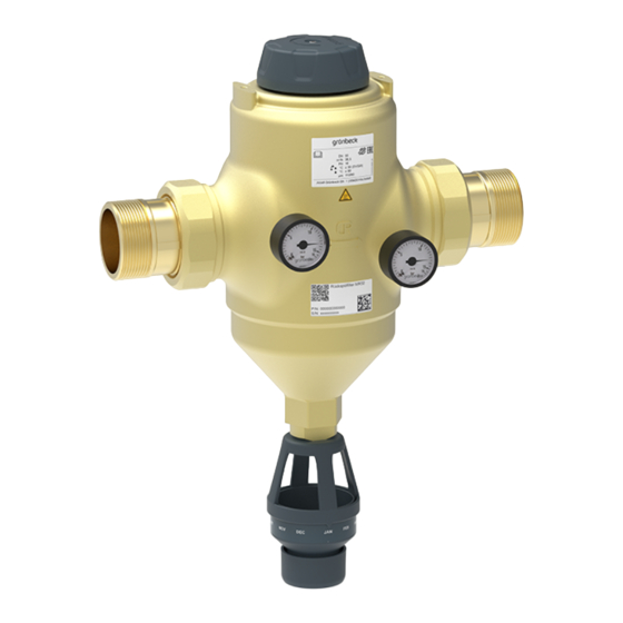
Product description Product components Designation Designation Water meter screw connection Filter element Seal O-ring of filter element Filter housing O-ring of filter funnel Backwash handwheel Filter funnel Pressure gauge inlet pressure Flange connection Outlet pressure gauge Flat seal Brush Double socket Sieve bottom Flushing water connection with free outlet Suction nozzle... -
Page 13: Functional Description
Product description Functional description The unfiltered raw water flows into the filter from the inlet side and from the inside out through the filter element and to the pure water outlet. Thus, foreign particles of > 100 µm in size are retained. Depending on their size and weight, foreign particles stick to the filter element, or they fall straight down into the filter funnel. -
Page 14: Accessories
Product description Accessories Your product can be retrofitted with accessories. Please contact your local Grünbeck repre- sentative or Grünbeck’s headquarters in Hoechstaedt/Germany for details. As per DIN EN 13433-1, filter elements with pore sizes of 50 μm, 200 μm and 500 μm are not permitted for drinking water systems and might only be used after consultation with Grünbeck. -
Page 15: Transport And Storage
Transport and storage Transport and storage Dispatch/delivery/packaging The product is packed in a cardboard box at the factory and secured with a foam bag. ► Check immediately upon receipt for completeness and transport damage. ► In case of visible transport damage, proceed as follows: •... -
Page 16: Installation
Installation Installation The installation of the product represents a major intervention into the drinking water sys- tem and must be carried out by a qualified specialist only. In accordance with DIN EN 806-2 and DIN EN 1717, the product is to be installed in the wa- ter pipe downstream of the water meter and upstream of distribution pipes and the appli- ances to be protected. -
Page 17: Requirements For The Installation Site
Installation Installation example: Backwash filter with flange connections Designation Designation Inlet shut-off valve Drain connection provided by the client on site Outlet shut-off valve Optional adapter kit Requirements for the installation site Obey the local installation directives, general guidelines and technical specifications. ●... -
Page 18: Checking The Scope Of Supply
Installation Required space ● Clearance above the filter head for operation ≥ 80 mm ● Clearance downwards for removal of the filter element (refer to chapter 12) ● Clearance at the front for operation ≥ 500 mm Water installation ● Floor drain or corresponding safety device with water stop function ●... -
Page 19: Water Installation
Installation Water installation The filter must only be installed horizontally and free of mechanical stress. ► Use protective gloves and protective footwear during the installation. ► Install the filter with an auxiliary person. In case of hot water filtration WARNING Hot water and hot surfaces ●... - Page 20 Installation ► Refit the filter’s pressure gauges, if necessary: Designation Designation Closing plug Pressure gauges for inlet and outlet pressure 1. Unscrew the closing plugs with O-ring as well as the pressure gauges. 2. Rotate the filter 180°. 3. Fit the closing plugs with O-ring and the pressure gauges. »...
- Page 21 Installation Installing the backwash filter (MR 1" – 2") with screw connections 5.4.2 1. Install the water meter screw connection in the pipe. » The distance between the two seals must have the dimensions below: 1"/ 1¼" = 190 mm and for 1½"/ 2" = 206 mm 2.
- Page 22 Installation Installing the backwash filter (MR DN 65 – DN 100) with flange connection 5.4.3 The backwash filters MR DN 65, DN 80 and DN 100 are designed with flange connection PN 16 according to DIN EN 1092-1. ► Comply with the Technical specifications for the flange connection (refer to chapter 12.5).
- Page 23 Installation 2. Position the filter in the pipe. a Pay attention to the marking of the flow direction on the filter. 3. Tighten the filter at the flange screw connections without applying tension. The on-site butterfly valves must open and close completely. a If necessary, install an (optional) adapter kit to ensure the function of the butter- fly valves.
- Page 24 Installation 5.4.4 Installing the connection for the backwash water If it is not possible to install a waste water pipe, the backwash water can be collected in a bucket/container. CAUTION Splashing hot water during backwash ● Scalding in case of hot water filtration without waste water pipe. ►...
- Page 25 Installation 5.4.4.2 Installing the drain connection and the waste water pipe Designation Designation Waste water pipe to be provided by the client Drain connection DN 50 on site on site ► Install a drain connection (not included in the scope of supply). ►...
-
Page 26: Start-Up
Start-up Start-up The initial start-up of the product must be carried out by a qualified specialist only. Closing the drain outlet Upon delivery, the drain outlet of the backwash filters is open. Designation Designation Backwash handwheel: Backwash handwheel: Direction of rotation for opening the drain out- Direction of rotation for closing the drain outlet ►... -
Page 27: Checking The Product
Start-up Checking the product ► Carry out the steps below after installation and after each maintenance: 1. Open the shut-off valves. 2. Open the nearest water withdrawal point after the filter as far as it will go. a Apply the maximum operating pressure. »... -
Page 28: Setting The Month Indicator
Start-up Setting the month indicator Via Grünbeck’s myProduct app, you will receive a message about the timely backwash of the filter (refer to chapter 7.3). Designation Maintenance ring ► Set the maintenance ring to the month of the next maintenance (alternatively, to the month of the next backwash –... -
Page 29: Operation/Handling
Operation/handling Operation/handling The filter is operated automatically and does not require any manual operation. ► Carry out a backwash at regular intervals (refer to chapter 7.3) ► Inspect the filter at regular intervals (refer to chapter 8.3). ► Flush the filter after a temporary standstill (refer to chapter 10.1). Installing Grünbeck’s myProduct app You can register your product using Grünbeck’s myProduct app. -
Page 30: Reading The Water Pressure
Operation/handling Reading the water pressure You can see on the pressure gauges whether the filter element is dirty. Designation Designation Inlet pressure Outlet pressure 1. Open several water withdrawal points (generate max. flow rate). 2. Read the inlet and outlet pressure on the pressure gauges. 3. -
Page 31: Backwashing The Filter
Operation/handling Backwashing the filter WARNING Irregular backwash of the filter ● Health risk due to contamination of the drinking water. ► Comply with the intervals for inspection and backwash of the filter. During the backwash process, filtered pure water is still available. We recommend repeating the backwash process 3 times. -
Page 32: Maintenance And Repair
Maintenance and repair Maintenance and repair Maintenance and repair includes the cleaning, inspection and servicing of the product. The responsibility for inspection and maintenance is subject to local and national require- ments. The owner/operating company is responsible for compliance with the prescribed maintenance and repair work. -
Page 33: Inspection
Maintenance and repair The interval table below shows the minimum intervals for the activities to be carried out. Activity Interval Tasks • 2 months Visual/functional check Inspection • Reading the water pressure • Carry out backwash Maintenance 6 months • Condition and leak test •... -
Page 34: Maintenance
Maintenance and repair Maintenance Some regular work is necessary to ensure the proper functioning of the product in the long term. DIN EN 806-5 recommends regular maintenance to ensure trouble-free and hygienic operation of the product. Contaminated drinking water due to contamination during maintenance WARNING and repair work ●... - Page 35 Maintenance and repair 8.4.2.1 Preparations 1. Close the shut-off valves at the inlet and outlet. 2. Carry out a backwash to relieve the water pressure in the filter and in the water pipe. » The filter is drained. 3. Remove the drain connection (if present). 8.4.2.2 Opening and checking the filter Designation...
- Page 36 Maintenance and repair a Clean the thread and the O-ring and apply food-safe grease, e.g. UNI-Silicon L641 (order no. 128 619). Designation Designation O-ring inside (Ø 89 mm) Brushes O-ring outside (Ø 98 mm) 6. Remove the filter element. 7. Check the brush/es for wear and tear. 8.
- Page 37 Maintenance and repair 8.4.2.3 Closing the filter 1. Fit the O-rings to the filter elements. Slide the filter elements with the larger Ø pointing forward over the suction nozzle into the filter housing. 2. Position the sieve bottom between the pipe nozzle and the lower suction nozzle. 3.
- Page 38 Maintenance and repair 6. Check the tight fit of the flushing water connection and the double socket. a Clean the nozzle screw with citric acid if there are deposits and impurities. 7. Install the drain connection (if present). 8.4.2.4 Putting the filter back into operation 1.
-
Page 39: Spare Parts
Maintenance and repair Spare parts For an overview of the spare parts, refer to our spare parts catalogue at www.gruenbeck.com. You can obtain the spare parts from your local Grünbeck representative. As per DIN EN 13433-1, filter elements with pore sizes of 50 μm, 200 μm and 500 μm are not permitted for drinking water systems and can only be used after consultation with Grünbeck (refer to Accessories 3.4). -
Page 40: Fault
Fault Fault WARNING Contaminated drinking water due to stagnation ● Infectious diseases ► Have malfunctions eliminated immediately. Observations Observation Explanation Remedy ► Fully open shut-off valves Water pressure at withdrawal point Shut-off valves are not fully open too low, Filter element is dirty ►... - Page 41 Fault Observation Explanation Remedy ► Check the filter for foreign par- Backwash handwheel cannot be Mechanical blockage in the filter operated or is difficult to move ticles and damage to interior parts ► Replace brush/es, if necessary ► Check the thread of the suc- Thread of suction nozzle is worn tion nozzle for wear and tear ►...
-
Page 42: Decommissioning
Decommissioning Decommissioning It is not necessary to take your product out of operation. In case of longer absences, e.g. holidays, precautionary hygiene measures according to VDI 3810-2 and VDI 6023-2 must be taken in order to maintain drinking water hygiene af- ter periods of standstill. -
Page 43: Dismantling And Disposal
Dismantling and disposal Dismantling and disposal 11.1 Dismantling The following work must be carried out by qualified specialists only. 1. Close the shut-off valves upstream and downstream of the filter. 2. Open a water withdrawal point. » The pressure in the pipe network is being relieved. 3. - Page 44 Dismantling and disposal Product If this symbol (crossed-out wheelie bin) is on the product, this product or its electrical and electronic components must not be disposed of as household waste. ► Find out about local regulations on the separate collection of electrical and elec- tronic products.
-
Page 45: Technical Specifications
Technical specifications Technical specifications 12.1 Backwash filters MR25/MR32 Dimensions and weights MR25 MR32 Total height Installation with screw connection length without screw connection Overall height above centre of connection Overall height up to centre of connection ≥ 215 ≥ 215... -
Page 46: Pressure Loss Curves Of Mr25 (1") And Mr32 (1¼")
R-15.2.3-21-17496 The Office of the Vienna Provincial Government – City of R-15.2.1-22-17624 Vienna Order no. 107000010000 107000020000 12.2 Pressure loss curves of MR25 (1") and MR32 (1¼") Designation Designation Pressure loss in bar Flow rate in m 46 | 56... -
Page 47: Backwash Filters Mr40/Mr50
Technical specifications 12.3 Backwash filters MR40/MR50 Dimensions and weights MR40 MR50 Total height Installation with screw connection length without screw connection Overall height above centre of connection Overall height up to centre of connection ≥ 215 ≥ 215 Clearance required for the replacement of the filter element ≥... -
Page 48: Pressure Loss Curves Of Mr40 (1½") And Mr50 (2")
Technical specifications Performance data MR40 MR50 Nominal pressure PN 16 Consumption data MR40 MR50 Backwash water volume at a water pressure of 3 ~ 40 bar and a backwash time of 1.5 min Backwash volume flow at 9 bar ~ 4.0 Allowable differential pressure General data MR40... -
Page 49: Backwash Filters Mr65/Mr80/Mr100
Technical specifications 12.5 Backwash filters MR65/MR80/MR100 Dimensions and weights MR65 MR80 MR100 Total height Installation length without counter- flanges; flanges PN 16 acc. to DIN EN 1092-1 Overall height above centre of connec- tion Overall height up to centre of connec- tion ≥... - Page 50 Technical specifications Connection data MR65 MR80 MR100 Nominal connection diameter DN 65 DN 80 DN 100 Drain connection DN 50 Performance data MR65 MR80 MR100 Nominal flow at p 0.2 (0.5) bar m³/h 37 (58) 60 (96.5) 60 (98) Kv value m³/h Pore size µm...
-
Page 51: Pressure Loss Curves Of Mr65/Mr80/Mr100
Technical specifications 12.6 Pressure loss curves of MR65/MR80/MR100 Designation Designation Pressure loss in bar Flow rate in m 51 | 56... -
Page 52: Operation Log
Operation log Operation log ► Document the initial start-up and all maintenance activities. ► Copy the maintenance report. Backwash filter MR ______________ Serial no.: _____________________ 13.1 Start-up log Customer Name Address Installation/accessories Drain connection acc. to DIN EN 1717 Floor drain present Safety device Operating values Water pressure raw water inlet... -
Page 53: Maintenance
Operation log 13.2 Maintenance Date Work performed Signature 53 | 56... - Page 54 Operation log Date Work performed Signature 54 | 56...
- Page 55 Publisher's information Technical documentation If you have any questions or suggestions regarding this operation manual, please contact the Technical Documentation Department at Grünbeck Wasserauf- bereitung GmbH Email: dokumentation@gruenbeck.de...
- Page 56 Grünbeck Wasseraufbereitung GmbH Josef-Grünbeck-Str. 1 89420 Hoechstaedt/Germany +49 9074 41-0 +49 9074 41-100 info@gruenbeck.com For more information www.gruenbeck.com go to www.gruenbeck.com...
Need help?
Do you have a question about the MR25 and is the answer not in the manual?
Questions and answers