Toshiba RAV-HM301SDTY-E Service Manual
Hide thumbs
Also See for RAV-HM301SDTY-E:
- Owner's manual (28 pages) ,
- Owner's manual (136 pages) ,
- Installation manual (41 pages)

Related Manuals for Toshiba RAV-HM301SDTY-E


Summary of Contents for Toshiba RAV-HM301SDTY-E
- Page 1 FILE NO. A10-2210 SERVICE MANUAL AIR-CONDITIONER SPLIT TYPE INDOOR UNIT <DIGITAL INVERTER> RAV-HM301SDTY-E RAV-HM401SDTY-E RAV-HM561SDTY-E RAV-HM801SDTY-E RAV-HM561SDTY-TR RAV-HM801SDTY-TR...
-
Page 2: Table Of Contents
NOTE A direct current motor is adopted for indoor fan motor in the Compact Slim Duct Type air conditioner. Caused from its characteristics, a current limit works on the direct current motor. When replacing the high-performance filter or when opening the service board, be sure to stop the fan. If an above action is executed during the fan operation, the protective control works to stop the unit operation, and the check code “P12”... - Page 3 9. ADDRESS SETUP..................67 9-1. Address Setup ....................67 9-2. Address Setup & Group Control..............68 9-3. Address Setup (Manual Setting from Remote Controller)......70 9-4. Confirmation of Indoor Unit No. Position ............71 10. DETACHMENTS ..................72 10-1. Indoor Unit ...................... 72 11.
-
Page 4: Original Instruction
Toshiba Carrier Corporation or, alternatively, he or she has been instructed in such matters by an individual or individuals who have been trained and is thus thoroughly acquainted with the knowledge related to this work. - Page 5 Definition of Protective Gear When the air conditioner is to be transported, installed, maintained, repaired or removed, wear protective gloves and ‘safety’ work clothing. In addition to such normal protective gear, wear the protective gear described below when undertaking the special work detailed in the table below.
-
Page 6: Warning Indications On The Air Conditioner Unit
Warning Indications on the Air Conditioner Unit [Confirmation of warning label on the main unit] Confirm that labels are indicated on the specified positions If removing the label during parts replace, stick it as the original. Warning indication Description WARNING WARNING ELECTRICAL SHOCK HAZARD ELECTRICAL SHOCK HAZARD... -
Page 7: Precaution For Safety
Precaution for Safety The manufacturer shall not assume any liability for the damage caused by not observing the description of this manual. DANGER Before carrying out the installation, maintenance, repair or removal work, be sure to set the circuit breaker to the OFF position. Otherwise, electric shocks may result. Before opening the electrical control box cover of the indoor unit or service panel of the outdoor unit, set the circuit breaker to the OFF position. - Page 8 Electrical wiring work shall be conducted according to law and regulation in the community and Installation manual. Failure to do so may result in electrocution or short circuit. To connect the electrical wires, repair the electrical parts or undertake other electrical jobs, wear gloves to provide protection for electricians, insulating shoes and clothing to provide protection from electric shocks.
- Page 9 Connect the cut-off lead wires with crimp contact, etc, put the closed end side upward and then apply a water-cut method, otherwise a leak or production of fire is caused at the users' side. Insulating measures When performing repairs using a gas burner, replace the refrigerant with nitrogen gas because the oil that coats the pipes may otherwise burn.
- Page 10 When the refrigerant gas leaks, find up the leaked position and repair it surely. If the leaked position cannot be found up and the repair work is interrupted, pump-down and tighten the service valve, otherwise the refrigerant gas may leak into the room. The poisonous gas generates when gas touches to fire such as fan heater, stove or cocking stove though the refrigerant gas itself is innocuous.
- Page 11 Only a qualified installer or service person is allowed to do installation work. Inappropriate installation may result in water leakage, electric shock or fire. Before starting to install the air conditioner, read carefully through the Installation Manual, and follow its instructions to install the air conditioner. If the unit is installed in a small room, take appropriate measures to prevent the refrigerant from exceeding the limit concentration even if it leaks.
- Page 12 Explanations given to user • If you have discovered that the fan grille is damaged, do not approach the outdoor unit but set the circuit breaker to the OFF position, and contact a qualified service person to have the repairs done. Do not set the circuit breaker to the ON position until the repairs are completed.
- Page 13 Specifications Sound pressure level (dB(A)) Model Weight (kg) Cooling Heating RAV-HM301SDTY-E RAV-HM401SDTY-E RAV-HM561SDTY-E RAV-HM801SDTY-E RAV-HM561SDTY-TR RAV-HM801SDTY-TR * Under 70 dBA – 13 –...
- Page 14 Refrigerant R32 This air conditioner adopts a new HFC type refrigerant (R32) which does not deplete the ozone layer. 1. Safety Caution Concerned to Refrigerant R32 Be sure that water, dust, the former refrigerant or the former refrigerating oil is not mixed into the refrigerating cycle of the air conditioner with refrigerant R32 during installation work or service work.
- Page 15 <Caution items> 1) The opposite side dimension of the air-conditioner’s flared nut using R32 and the shape of the charge port are the same as those of R410A. 2) Be careful not to charge refrigerant by mistake. Should the different type of refrigerant mix in, be sure to recharge the refrigerant 3) Do not mix the other refrigerant or refrigerating oil with the refrigerant.
- Page 16 4. Tools : R410A tools available : Partly unavailable, : R410A tools unavailable Installation/service tools Applicability to R32 air Applicability to R22 air conditioner or not conditioner or not Tools / Equipment specification 1 Flare tool Clutch type Pipe flaring Copper pipe gauge for Flaring by adjusting projection...
-
Page 17: Air Ducting Work
1. AIR DUCTING WORK 1-1. Static Pressure Characteristics 301 type 401 type Standard air volume: 570 (m Standard air volume: 600 (m Upper limit of external High (50Pa) static pressure (50Pa) High (50Pa) Upper limit of external static pressure (50Pa) Lower limit of Lower limit of external static... -
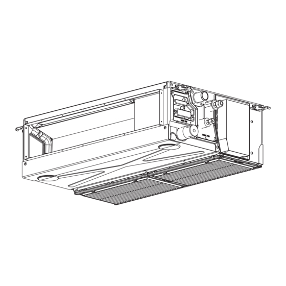
Page 18: Construction Views (External Views)
2. CONSTRUCTION VIEWS (EXTERNAL VIEWS) – 18 –... -
Page 19: Wiring Diagram
3. WIRING DIAGRAM WIRING DIAGRAM 3~ Color Indication RED:RED BLU:BLUE WHI:WHITE BLK:BLACK CN210 YEL:YELLOW GRN:GREEN SW501 CN504 (WHI) BRW:BROWN (External static CN34 T6.3A (WHI) pressure setup) (RED) 250V Main P.C.Board CN104 t° MCC-1643 (YEL) CN22 CN67 CN102 t° (BLK) (RED) TB01 (CHK) CN71... -
Page 20: Specifications Of Electrical Parts
4. SPECIFICATIONS OF ELECTRICAL PARTS Compact Slim Duct Type Type Output (Rated) 50W Fan motor ICF-340WD50-1 Fan motor ICF-340WD94-3 Output (Rated) 94W Thermo. Sensor (TA-sens or) 328mm 10kΩ at 25°C Ø6mm, 1000mm 10kΩ at 25°C Heat exchanger sensor (TCJ-sensor) Heat exchanger sensor (TC-sensor) Ø6mm, 1000mm 10kΩ... -
Page 21: Control Block Diagram
5. CONTROL BLOCK DIAGRAM 5-1. Indoor Controller Block Diagram 5-1-1. In Case of Connection of Wired (Simple) Remote Controller Indoor Unit Control Unit M.C.U. Heat Exchanger Sensor (Tcj) Functions Float input Heat Exchanger Sensor (Tc) • Cold draft preventing Function Drain pump Room Temperature Sensor (Ta) •... -
Page 22: Control Specifications
5-2. Control Specifications Item Outline of specifications Remarks When power 1) Distinction of outdoor unit supply is reset When the power supply is reset, the outdoors are distin- guished and the control is selected according to the distinguished result. 2) Setting of indoor fan speed and existence of air direction adjustment Based on EEPROM data, select setting of the indoor fan speed. - Page 23 Item Outline of specifications Remarks Room temp. 2) Using the CODE No. 06, the setup temperature in heating Shift of suction control operation can be corrected. temperature in heating (Continued) operation SET DATA Setup temp. +0°C +2°C +4°C +6°C correction Setting at shipment SET DATA Automatic...
- Page 24 Item Outline of specifications Remarks Fan speed control 1) Operation with (HH), (H), (L) or [AUTO] mode is carried HH > H+ > H > L+ > out by the command from the remote controller. L > UL 2) When the fan speed mode [AUTO] is selected, the fan speed varies by the difference between Ta and Ts.
- Page 25 Item Outline of specifications Remarks Fan speed control (Continued) CODE No. 10Pa 20Pa 25Pa 35Pa 50Pa 60Pa 45Pa [5d] 0000 0001 0002 0003 0004 0005 0006 SW501(1)/(2) OFF/OFF ON/OFF OFF/ON ON/ON COOL HEAT COOL HEAT COOL HEAT COOL HEAT COOL HEAT COOL HEAT...
- Page 26 Item Outline of specifications Remarks Tcj: Freeze preventive control 1) The cooling operation (including Dry operation) is (Low temperature release) performed as follows based on the detected Indoor heat exchanger temperature of Tc sensor or Tcj sensor. sensor temperature When [J] zone is detected for 6 minutes (Following figure), the commanded frequency is decreased from the real operation frequency.
- Page 27 Item Outline of specifications Remarks High-temp. 1) The heating operation is performed as follows based on the release control detected temperature of Tc sensor or Tcj sensor. • When [M] zone is detected, the commanded frequency is However this control is decreased from the real operation frequency.
- Page 28 Item Outline of specifications Remarks <In case of wired remote controller> Frequency Command frequency is fixed operation approximately [S7] 1) When pushing [CHK] button for 4 seconds or more, [TEST] is (Test run) displayed on the display screen and the mode enters in Test run mode.
- Page 29 Item Outline of specifications Remarks Energy-saving 1) Selecting [AUTO] mode enables an energy-saving to control be operated. 2) The setup temperature is shifted (corrected) in the range not to lose the comfort ability according to input values of various sensors. 3) Data (Input value room temp.
- Page 30 Item Outline of specifications Remarks DC motor 1) When the fan operation has started, positioning of the stator and the rotor are performed. (Moves slightly with tap sound) 2) The motor operates according to the command from the indoor controller. Notes) •...
- Page 31 Item Outline of specifications Remarks This function depends Save operation 1) The current release control is performed with the on remote controller restriction ratio set in EEPROM on the outdoor unit. 2) Setting method: push and hold [MENU] and [▼] buttons on the remote controller for at least 10 seconds to enter DN setting, adjust CODE No.
-
Page 32: Indoor Print Circuit Board
5-3. Indoor Print Circuit Board <MCC-1643> Power supply LED of Wired remote controller HA(T10) microprocessor communication LED DC fan motor CN61(Yellow),DC12V D501(Red) D504(Green) CN210(White) TA sensor CN104(Yellow),DC5V Drain pump CN504(White),DC12V Power supply CN67(Black),AC220V TC sensor CN101(Black),DC5V TCJ sensor CN102(Red),DC5V Float SW CN34(Red),DC12V Serial signal transmit D15(Green) - Page 33 Optional Connector Specifications of Indoor P.C. Board (MCC-1643) Connector Function Specifications Remarks ① CN61 ON/OFF input HA ON/OFF input (J01: YES/NO=Pulse (At shipment from factory) / Static input selection) ② ③ Remote controller Permission/Prohibition of remote controller operation stop is performed by input. prohibited input ④...
-
Page 34: Troubleshooting
6. TROUBLESHOOTING 6-1. Summary of Troubleshooting <Wired remote controller type> 1. Before troubleshooting 1) Required tools/instruments – • screwdrivers, spanners, radio cutting pliers, nippers, push pins for reset switch • Tester, thermometer, pressure gauge, etc. 2) Confirmation points before check a) The following operations are normal. - Page 35 Outline of judgment When one of the following phenomena appears, an error of the power relay (RY01) is considered; therefore replace the P.C. board. • The operation • The fan stops immediately. After approx. 1minute The screen of the → →...
- Page 36 Lamp indication Check code Cause of trouble occurrence Operation Timer Ready Heat exchanger sensor (TCJ) error Heat exchanger sensor (TC) error Indoor unit sensor error Alternate flash Heat exchanger sensor (TA) error Discharge temp. sensor (TD) error ...
- Page 37 Others (Other than Check Code) Lamp indication Check code Cause of trouble occurrence Operation Timer Ready — During test run Simultaneous flash Operation Timer Ready Disagreement cool/heat — (Automatic cool/heat setting to automatic cool/heat prohibited mode) Alternate flash – 37 –...
-
Page 38: Check Code List (Indoor)
– 38 –... - Page 39 Check Code List Error mode detected by indoor unit Operation of diagnostic function Judgment and measures Check Status of Cause of operation Condition code air conditioner 1. Check cables of remote controller and communication adapters. Stop Displayed when No communication from remote •...
- Page 40 Error mode detected by outdoor unit Operation of diagnostic function Check code Judgment and measures Status of Cause of operation Condition air conditioner Indoor unit Disconnection, short of discharge temp. sensor 1. Check discharge temp. sensor (TD). Displayed when Stop (TD) error is detected 2.
- Page 41 Operation of diagnostic function Check code Status of Judgment and measures Cause of operation air conditioner Condition Indoor unit Displayed when 1. Check outdoor P.C. board. Current detection circuit error Stop error is detected (AC current detection circuit) Displayed when Open phase of 3-phase power supply Stop 1.
- Page 42 Error mode detected by remote controller Operation of diagnostic function Judgment and measures Status of Check code Cause of operation Condition air conditioner Power supply error of remote controller, Indoor EEPROM error 1. Check remote controller inter-unit wiring. No communication with master indoor unit 2.
-
Page 43: Diagnostic Procedure For Each Check Code (Indoor Unit)
6-3. Diagnostic Procedure for Each Check Code (Indoor Unit) Check code [E01 error] Correct inter-unit cable Is inter-unit cable of A and B normal? of remote controller Is there no disconnection or Correct connection of connector. contact error of connector on harness Check circuit wiring. - Page 44 [E04 error] Is group address setup of Does outdoor operate? Check CODE No. [14]. remote controller correct? Are wiring in indoor unit and Correct wiring and 1, 2, 3 inter-unit cables correct? inter-unit cables. Correct wiring of connector Are wirings of terminal blocks and terminal blocks.
- Page 45 [E18 error] Correct inter-unit cable Is inter-unit cable of A and B normal? of remote controller. Is there no disconnection Correct connection of connector. or contact error of connector on harness from terminal block Check circuit wiring. of indoor unit? Is group control operation? Check power connection status of indoor unit...
- Page 46 [L30 error] Check indoor P.C. board (MCC-1643). Are outside devices connected? Defect → Replace Check outside devices. Do outside devices normally work? Defect → Replace Check cause of operation. – 46 –...
- Page 47 [P10 error] Is connection of float switch connector Correct connection (Indoor control board CN34) of connector. normal? Does float switch work? Is circuit wiring normal? Check and correct wiring and wire circuit. Does drain pump work? Are connector pins 1 and 2 Is power of at drain pump unit side shorted drain pump turned on? ∗...
- Page 48 [P12 error] Power off. Is not connection error or Repair the connector disconnection on the connector connection. CN210 of indoor unit P.C. board? Disconnect the connector CN210 to the indoor P.C. board Does the Replace the indoor fan turn smoothly when fan motor.
- Page 49 [P19 error] Is operation of 4-way valve normal? Are 1.3 to 1.6k Ω applied to (Check the pipe temp., etc. Replace 4-way valve coil. resistance value of 4-way valve coil ? during cooling/heating operation. Defective Check outdoor P.C. board operation. Check outdoor P.C.
- Page 50 [F02 error] Is connection of TC sensor connector Correct connection of connector. (CN101 on Indoor P.C. board) correct? Are characteristics of Replace TC sensor. TC sensor resistance value normal? ∗ Refer to Charqacteristics-2. Check indoor P.C. board (MCC-1643). Defect → Replace [F01 error] Is connection of TCJ sensor connector Correct connection of connector.
- Page 51 [E03 error] (Master indoor unit) [E03 error] is detected when the indoor unit cannot receive a signal from the wired remote controller. [F29 error] This check code indicates a detection error of IC503 non-volatile memory (EEPROM) on the indoor unit P.C. board, which generated during operation of the air conditioner.
- Page 52 Temperature – Resistance value characteristic table TA, TC, TCJ, TE, TS, TO sensor TD, TL sensor Representative value Representative value Resistance value (kΩ Ω Ω Ω Ω ) Resistance value (kΩ Ω Ω Ω Ω ) Temperature Temperature (Minimum (Standard (Maximum (Minimum (Standard...
- Page 53 Winding Resistance of Fan Motor Compact Slim Duct Type Measure the resistance value of each winding by using the tester. Fan motor Fan motor inside wiring diagram Position Resistance value Black – Red 37.7 ± 3.8 Black – White 37.7 ± 3.8 White Red –...
-
Page 54: Replacement Of Service P.c. Board
7. REPLACEMENT OF SERVICE P.C. BOARD 7-1. Indoort Unit CAUTION <Model : RAV-HM***SDTY-E(TR)> For the above models, set the CODE No. to “ ” and the setting data to “0004”. <Note: when replacing the P.C. board for indoor unit servicing> The nonvolatile memory (hereafter called EEPROM, IC503) on the indoor unit P.C. - Page 55 The setting data modified on the site, other than factory-set value, stored in the EEPROM shall be read out. [1] Setting data read out from EEPROM TEST Step 1 Push buttons on the remote controller simultaneously for more than 4 seconds. The setting data modified on the site, other than factory-set value, stored in the EEPROM shall be read out.
- Page 56 [3] Writing the setting data to EEPROM The settings stored in the EEPROM of the P .C. board for indoor unit servicing are the factory-set values. Step 1 In STOP status, push [MENU] and [▼] buttons simultaneously for at least 10 seconds. •...
- Page 57 Table 1 Item Setting data Factory-set value Filter sign lighting time Depending on Type Filter pollution level 0000: standard Heating suction temperature shift 0002: +2°C Cooling only 0000: Heat pump Type Depending on model type Indoor unit capacity Depending on capacity type System address 0099: Not determined Indoor unit address...
-
Page 58: Setup At Local Site And Others
8. SETUP AT LOCAL SITE AND OTHERS 8-1. Indoor Unit 8-1-1. Test Run Setup on Remote Controller <Wired remote controller> 1. Push [TIME] and [▲] buttons and hold for more than 10 seconds. [TEST] is displayed on the display screen, and mode selection in Test mode is allowed. - Page 59 8-1-2. Forced Defrost Setup of Remote Controller (For wired remote controller only) (Prepare in advance) Push [MENU] and [▼] buttons simultaneously for at least 10 seconds. • In the air-conditioning group control mode, and the indoor unit No. are displayed. The indoor unit number displayed first is the main indoor unit number.
- Page 60 8-1-4. Function Selection Setup <Procedure> Perform setting while the air conditioner stops. In STOP status push [MENU] and [▼] buttons simultaneously for at least 10 seconds. • In the air-conditioning group control mode, and the indoor unit No.1-N are displayed first. 1 is the piping system address (the value of the refrigerant piping system is the same as the number of outdoor units, and one outdoor unit is displayed as 1).
- Page 61 Item No. (DN) table (Selection of function) Item Description At shipment Filter sign lighting time} 0000 : None 0002 : 2500H 0002 : 2500H (4-Way/Duct/Ceiling Type) Dirty state of filter 0000 : Standard 0001 : High degree of dirt 0000 : Standard (Half of standard time) Heating suction temp shift 0000 : No shift...
- Page 62 Item Description At shipment Timer set 0000 : Available (Operable) 0000 : Available (Wired remote controller) 0001 : Unavailable (Operation prohibited) Correction of high heat feeling 0000 : None 0001 : Correction 0000 : None 0000: None Self clean time 0000: None 0001: 0.5h to 0.012: 6.0h The case that compressor-ON time is 10 to 60 minutes is...
- Page 63 8-1-5. Wiring and Setting of Remote Controller Control 2-remote controller control (Controlled by 2 remote controllers) This control is to operate 1 or multiple indoor units are operated by 2 remote controllers. (Max. 2 remote controllers are connectable.) • When connected 2 remote controllers operate an indoor unit Remote controller Remote controller switch (Master)
- Page 64 8-1-6. Monitor Function of Remote Controller Switch Calling of sensor temperature display <Contents> Each data of the remote controller, indoor unit and outdoor unit can be understood by calling the service monitor mode from the remote controller. Push and hold [MENU] button for at least 10 seconds to call the service monitor mode.
- Page 65 Calling of error history <Contents> The error contents in the past can be called. <Procedure> Push and hold [TIME] button for more than 10 seconds, and an indicator icon appears, indicating it is in the troubleshooting history mode. • [01] (01-04: Error record sequence) is displayed at CODE No. •...
- Page 66 Indoor unit power-ON sequence • The unit without power feed waits entirely → Waiting status is released by system start Power ON • Reboot when power is fed on the way <By indoor unit which receives power feed from outdoor unit> <Automatic address judgment>...
-
Page 67: Address Setup
9. ADDRESS SETUP 9-1. Address Setup <Address setup procedure> When an outdoor unit and an indoor unit are connected or when an outdoor unit is connected to each indoor unit respectively in the group operation, the automatic address setup completes with power-ON of the outdoor unit. -
Page 68: Address Setup & Group Control
9-2. Address Setup & Group Control <Terminology> Indoor unit No. : N – n = Outdoor unit line address N (Max. 30) – Indoor unit address n (Max. 64) Group address : 0 = Single (Not group control) 1 = Header unit in group control 2 = Follower unit in group control Header unit (= 1) : The representative of multiple indoor units in group operation sends/receives signals to/ from the remote controllers and follower indoor units. - Page 69 9-2-2. Automatic Address Example from Unset Address (No miswiring) 1. Standard (One outdoor unit) Individual (Header/Master) Only turning on source power supply (Automatic completion) 2. Group operation (Multiple outdoor units = Multiple indoor units with serial communication only) Header/Sub Header/Sub Header/Master Header/Sub (Max.
-
Page 70: Address Setup (Manual Setting From Remote Controller)
9-3. Address Setup (Manual Setting from Remote Controller) In case that addresses of the indoor units will be (Example of 4-lines wiring) (Real line: Wiring, Broken line: Refrigerant pipe) determined prior to piping work after wiring work Outdoor Outdoor Outdoor Outdoor •... -
Page 71: Confirmation Of Indoor Unit No. Position
9-4. Confirmation of Indoor Unit No. Position 1. To know the indoor unit addresses though position of the indoor unit body is recognized • In case of individual operation (Wired remote controller : indoor unit = 1 : 1) (Follow to the procedure during operation) <Procedure>... -
Page 72: Detachments
10. DETACHMENTS WARNING CAUTION Be sure to stop operation of the air conditioner before Be sure to put on gloves during working time; work and then turn off switch of the breaker. otherwise an injury will be caused by a part, etc. 10-1. - Page 73 Part name Procedure Remarks 2. Attachment Terminal cover 1) Insert the claws on the left side of the terminal cover into their slits. 2) Moving the terminal cover downward, insert the cover in the gap between the terminal box Slit and screw that you loosened in step 1-1) of “CTerminal cover”...
- Page 74 Part name Procedure Remarks Electric parts box 1. Detachment 1) For the back air intake, perform the procedure Electric parts box in 1 of “BSuction panel.” 2) Perform the procedure in 1 of “DElectric parts box cover.” 3) Remove the binding bands and clamps inside Binding band the electric parts box.
- Page 75 Part name Procedure Remarks 1. Detachment Control P.C. board 1) Perform the procedure in 1 of “DElectric parts box cover.” 2) Disconnect the connectors from other components from the control P.C. board. NOTE) Unlock the lock of the housing to disconnect the connectors.
- Page 76 Part name Procedure Remarks 1. Detachment Fan case (lower), Fan 1) For the back air intake, perform the procedure case (upper) in 1 of “BSuction panel.” Fan case (upper) 2) Remove the screw on the rear of the fan case Fan case (lower) screw (lower).
- Page 77 Part name Procedure Remarks 1. Detachment Fan motor, Multi blade fan 1) For the back air intake, perform the procedure in 1 of “BSuction panel.” 2) Perform the procedure in steps 1-1), 1-2), 1-3) Clamp of “DElectric parts box cover.” Binding band 3) Disconnect the following connector of the control P.C.
- Page 78 Part name Procedure Remarks NOTE) Fan motor, Multi blade fan Arrange the multi blade fan so that screws position at the right side against the drain pan. NOTE) Fix multi blade fan with torque wrench 4.9 N•m or more. 3) Perform the procedure in steps 2-3) and 2-4) of “HFan case (lower/upper)”...
- Page 79 Part name Procedure Remarks Under panel, 1. Detachment Drain pan 1) Tack off the drain cap and drain the drain water accumulated in the drain pan. Drain cap and Screws (Ø4x10) In case off natural drain model,drain the drain drain hose water by taking off hose band and drain hose.
- Page 80 Part name Procedure Remarks 1. Detachment Drain pump, *Some models have no float switch cover here. Float switch, 1) Perform the procedure in steps 1-1), 1-2), 1-3) Drain hose of “DElectric parts box cover” and 1 of Drain pump Float switch “JUnder panel, Drain pan.”...
- Page 81 Part name Procedure Remarks 1. Detachment Heat exchanger 1) Recover refrigerant, and then remove Sensors refrigerant pipes at indoor unit side. Binding band 2) Perform the procedure in steps 1-1), 1-2), 1-3) of “DElectric parts box cover” and 1 of “JUnder panel, Drain pan.”...
-
Page 82: Exploded Views And Parts List
11. EXPLODED VIEWS AND PARTS LIST – 82 –... - Page 83 RAV-HM***SDTY-E/TR Location No. Parts No. Description 43H22003 CASE,FAN,UPPER 43H22004 CASE,FAN,UPPER 43H22005 CASE,FAN,UPPER 43H22006 CASE,FAN,LOWER 43H22007 CASE,FAN,LOWER 43H22008 CASE,FAN,LOWER 43H21004 MOTOR,FAN 43H21011 MOTOR,FAN 43H00021 PLATE,INLET 43H00022 PLATE,INLET 43H00023 PLATE,INLET 43H70001 HOSE,DRAIN 43H44056 REFRIGERATION CYCLE ASSY 43H44057 REFRIGERATION CYCLE ASSY 43H44058 REFRIGERATION CYCLE ASSY 43H44059 REFRIGERATION CYCLE ASSY 43H49027 SOCKET 43H49028 SOCKET...
- Page 84 Electric parts HOLDER SENSOR(TA) PC BOARD ASSY MCC-1643 TERMINAL 3P REACTOR SENSOR TA SENSOR TC SENSOR TC TERMINAL 2P Location Description Parts No. RAV-HM***SDTY-E(TR) 43H58010 REACTOR 43H50010 SENSOR,TC 43H50011 SENSOR,TC 43H50012 SENSOR,TA 43H60013 TERMINAL,3P 43H60014 TERMINAL,2P 43H69102 PC BOARD ASSY, MCC-1643 43H63001 HOLDER,SENSOR(TA) –...
- Page 85 Toshiba Carrier Air Conditioning (China) Co., Ltd.
Need help?
Do you have a question about the RAV-HM301SDTY-E and is the answer not in the manual?
Questions and answers