
Related Manuals for Toshiba RAV-HM901FT-E


Summary of Contents for Toshiba RAV-HM901FT-E
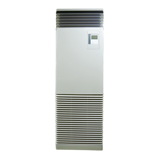
- Page 1 AIR CONDITIONER (SPLIT TYPE) Installation Manual For commercial use Indoor Unit Model name: <Floor Standing type> RAV-HM561FT-E RAV-HM801FT-E RAV-HM901FT-E RAV-HM1101FT-E RAV-HM1401FT-E RAV-HM1601FT-E English...
-
Page 2: Table Of Contents
Product information of ecodesign requirements. (Regulation (EU) 2016/2281) http://ecodesign.toshiba-airconditioning.eu/en 7 Electrical connection ..........16 8 Applicable controls . - Page 3 Toshiba Carrier Corporation or, alternatively, he or she has been instructed in such matters by an individual or individuals who have been trained and is thus thoroughly acquainted with the knowledge related to this work.
- Page 4 – 3 – Meanings of symbols displayed on the air conditioner Warning indications on the air conditioner unit Warning indication Description These safety cautions describe important matters concerning safety to prevent injury to users or other people and damages to property. Please read through this manual after understanding the contents below (meanings of indications), and be sure to follow the description.
-
Page 5: Precautions For Safety
Precautions for safety • When work is performed at heights, use a ladder which complies with the ISO 14122 standard, and follow the procedure in the ladder’s The manufacturer shall not assume any liability for the damage caused instructions. Also wear a helmet for use in industry as protective gear by not observing the description of this manual. - Page 6 – 5 – Selection of installation location • Tighten the flare nut with a torque wrench in the specified manner. • When the air conditioner is installed in a small room, provide Excessive tighten of the flare nut may cause a crack in the flare nut appropriate measures to ensure that the concentration of refrigerant after a long period, which may result in refrigerant leakage.
- Page 7 • Under no circumstances, the power supply wire or the indoor and Explanations given to user outdoor connecting wire must not be connected in the middle • Upon completion of the installation work, tell the user where the circuit (Connection using a solderless terminal etc.) breaker is located.
- Page 8 – 7 – CAUTION This Air Conditioner has adopted a refrigerant HFC (R32) which does not destroy the ozone layer. • As the R32 refrigerant is easily affected by impurities such as moisture, oxidized film, oil, etc., due to the high pressure, be careful not to allow the moisture, dirt, existing refrigerant, refrigerating machine oil, etc., to get mixed up in the refrigeration cycle during the installation work.
-
Page 9: Accessory Parts
Accessory parts Selection of installation place Attached position Part name Q’ty Shape Stored position WARNING Upper part of main unit Bracket for fixing to wall • Install the air conditioner securely in a location where the base can sustain the weight adequately. If the strength is not enough, the unit may fall down resulting in injury. - Page 10 – 9 – To open the intake grille • In the case of the wireless type of system, rooms with the inverter type of fluorescent lighting or locations exposed to direct sunlight. (The signals from the wireless remote controller may not be sensed.) •...
-
Page 11: Installation
Installation ■ External views (Unit: mm) Bracket for WARNING fixing to wall Positioning for refrigerant piping Discharge port Pitch Pitch • Install the air conditioner securely in a location where the base can sustain the weight adequately. If the strength is not 30×3 30×3 enough, the unit may fall down resulting in injury. - Page 12 – 11 – Installation of indoor unit Installation of wired remote controller (sold separately) Fixing to the floor Use the attached floor fixing bracket to fix the lower right and left sides of the indoor unit to the floor. REQUIREMENT CAUTION To fix to the indoor unit, use the side plate screws and...
- Page 13 <RBC-ASCU1 > (1) Mount the remote controller onto the rear case mounted on the mounting bracket in . (2). (2) Mount the remote controller panel onto the upper cabinet. This remote controller cannot be attached to the main unit. This remote controller is used by mounting it on a wall etc.
-
Page 14: Drain Piping
– 13 – Drain piping Installation of wireless remote controller (Sold separately) CAUTION CAUTION When installing a wireless remote controller, be sure to connect a wired remote controller to make a 2-remote controller • Following the Installation Manual, perform the drain piping work so that water is properly drained. Apply a system. - Page 15 Connecting drain pipe • To connect drain hose on left • To connect drain hose on right Drain pan Heat insulator Hard polyvinyl chloride pipe Refrigerant Drain pan Drain pan piping PVC pipe PVC pipe (Drain piping) (Drain piping) Drain hose Adhesion for hard polyvinyl chloride pipe used...
-
Page 16: Refrigerant Piping
– 15 – Refrigerant piping Tightening connection Evacuation Perform vacuuming from the charge port of valve of the Permissible piping length and CAUTION outdoor unit by using a vacuum pump. CAUTION For details, follow to the Installation Manual attached to height difference Do not apply excessive torque. -
Page 17: Electrical Connection
Electrical connection Gas leak check Check with a leak detector or soap water whether gas leaks or not, from the pipe connecting section or cap of WARNING the valve. • Use the specified wires for indoor and outdoor connecting wires. Securely fix them to prevent external forces REQUIREMENT applied to the terminals from affecting the terminals. - Page 18 – 17 – Communication type Wiring between indoor unit and outdoor unit TU2C-Link can be used with these models. 1. Figure below shows the wiring connections between the indoor and outdoor units and between the indoor units If the indoor unit and the connected remote controller / remote sensor are all TU2C-Link models, TU2C-Link and remote controller.
- Page 19 Wiring connection Remote controller wiring Strip off approx. 9 mm the wire to be connected. <Positioning of hole for wiring (Knock-out hole) > REQUIREMENT HM90 to HM160 Wiring diagram HM56, HM80 • Connect the wires matching the terminal numbers. Incorrect connection causes a trouble.
-
Page 20: Applicable Controls
– 19 – Applicable controls DN setting Applicable controls setup ∧ ∨ Push the [ ] / [ ] button to select REQUIREMENT Indoor unit (settings at the site) “7. DN setting” on the “Field setting menu” Code (DN) I.DN •... - Page 21 Filter sign setting 8°C operation Fan speed setting when thermostat-OFF in cooling According to the installation condition, the filter sign Pre-heating operation can be set for cold regions term (Notification of filter cleaning) can be changed. where room temperature drops to below zero. mode Follow to the basic procedure.
- Page 22 – 21 – Group control Group control for system of multiple units One group can control up to 16 (TU2C-Link) or 8 (TCC-Link) indoor units with one remote controller. (Refer to the Simultaneous twin, triple or double twin system Wiring specifications) A combination with an outdoor unit allows simultaneous ON / OFF operation of the indoor units.
- Page 23 [Procedure example] NOTE Manual address setup procedure Push the [ MENU] button to display the In some cases, it is necessary to change the address manually after setup of the automatic address according to the menu screen. While the operation stops, change the setup. system configuration of the group control.
-
Page 24: Test Run
– 23 – Test run Push the [ MENU] button to set the other Address is displayed here. Code (DN) and Data. After “Continue?” is displayed on the screen, push the DN setting “ Yes” [ F1] button. Code Before test run (DN) I.DN Data Indoor address change... - Page 25 Monitor function Room A 12:00 Push the [ ON / OFF] button to start the The sensor temperature or operational status of indoor unit, outdoor unit, or remote controller can be monitored. test mode. The screen (1) shown in the left Test appears.
-
Page 26: Maintenance
– 25 – Maintenance Push the [ ON / OFF] button to stop the Close the intake grille and fasten the screws operation, then turn off the circuit breaker. (two places). Be sure to turn off the circuit breaker before maintenance. Use a screwdriver to unfasten the screws of Turn on the circuit breaker, then push the the intake grille (two places) to open the... - Page 27 ▼Maintenance List CAUTION Part Unit Check (visual / auditory) Maintenance • Do not start the air conditioner while leaving air filter removed. Wash the heat exchanger when it is Heat exchanger Indoor / outdoor Dust / dirt clogging, scratches • Reset the filter sign. clogged.
-
Page 28: Troubleshooting
– 27 – Troubleshooting Check codes and parts to be checked Wireless remote controller Remote controller Sensor block display of Confirmation and check display receiving unit Judging Main defective parts Parts to be checked / trouble description conditioner device Operation Timer status... - Page 29 Remote Wireless remote controller Remote Wireless remote controller controller Sensor block display of controller Sensor block display of display display receiving unit receiving unit Judging Judging Main defective parts Parts to be checked / trouble description conditioner Main defective parts Parts to be checked / trouble description conditioner device...
- Page 30 – 29 – APPENDIX Minimum floor area: Amin (m²) Do not install the indoor unit in a poorly ventilated space that is smaller than the minimum floor area (Amin). For refrigerant quantity, refer to Fluorinated Greenhouse Gases label on the outdoor unit. For the minimum floor area (Amin) of this indoor unit, refer to table below.
- Page 31 EB99847901 (DH91308301)