Toshiba RAV-HM561UTP-E Installation Manual
Hide thumbs
Also See for RAV-HM561UTP-E:
- Owner's manual (17 pages) ,
- Engineering data book (114 pages)

Related Manuals for Toshiba RAV-HM561UTP-E


Summary of Contents for Toshiba RAV-HM561UTP-E
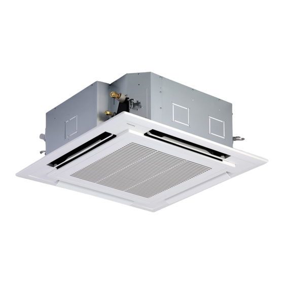
- Page 1 AIR CONDITIONER (SPLIT TYPE) Installation Manual Indoor Unit For commercial use Model name: 4-way Cassette type RAV-HM561UTP-E RAV-HM801UTP-E RAV-HM901UTP-E RAV-HM1101UTP-E RAV-HM1401UTP-E RAV-HM1601UTP-E English...
-
Page 2: Table Of Contents
Product information of ecodesign requirements. (Regulation (EU) 2016/2281) http://ecodesign.toshiba-airconditioning.eu/en Electrical connection ............13 Applicable controls . - Page 3 Toshiba Carrier Corporation or, alternatively, he or she has been (Risk of fire) If refrigerant leaks and comes in contact with fire or heating part, it will...
-
Page 4: Precautions For Safety
– 3 – Precautions for safety Warning indications on the air conditioner unit The manufacturer shall not assume any liability for the damage caused by not observing the description of this manual. Warning indication Description WARNING WARNING WARNING ELECTRICAL SHOCK HAZARD General ELECTRICAL SHOCK HAZARD Disconnect all remote... - Page 5 • Wear protective gloves and safety work clothing during Selection of installation location installation, servicing and removal. • When the air conditioner is installed in a small room, provide • Do not touch the aluminium fi n of the unit. You may injure appropriate measures to ensure that the concentration of yourself if you do so.
- Page 6 – 5 – • If refrigerant gas has leaked during the installation work, Electrical wiring • Only a qualifi ed installer(*1) or qualified service person(*1) is ventilate the room immediately. If the leaked refrigerant gas allowed to carry out the electrical work of the air conditioner. comes in contact with fi...
- Page 7 Test run • After the installation work, follow the Owner’s Manual to explain • Before operating the air conditioner after having completed the to the customer how to use and maintain the unit. work, check that the electrical control box cover of the indoor Relocation unit and service panel of the outdoor unit are closed, and set •...
-
Page 8: Accessory Parts
– 7 – Accessory parts Selection of installation place WARNING Part name Q’ty Shape Usage (Hand over to customers) • Install the air conditioner at enough strong place to withstand the weight of the unit. Installation Manual This manual (For other languages that do not appear in this Installation Manual, If the strength is not enough, the unit may fall down resulting in injury. - Page 9 Installation space When the height of the ceiling exceeds the distance of the item Standard / 4-way in Table as below, the hot air is (Unit : mm) diffi cult to reach the fl oor. Therefore, it is necessary to change the setup value of the high ceiling switch or discharge direction. Secure the specifi...
-
Page 10: Installation
– 9 – Installation Opening a ceiling and Treatment of ceiling installation of hanging bolts The ceiling differs according to structure of building. REQUIREMENT For details, consult your constructor or interior finish Strictly comply with the following rules to prevent damage of the indoor units and human injury. Consider the piping / wiring before the unit is hung contractor. - Page 11 Installation of ceiling panel In case of wireless type Level vial (levelness: 5 mm or less) Installation of ceiling opening and Hanging bolt Indoor unit (Sold separately) hanging bolt The sensor of indoor unit with wireless remote controller can receive a signal by distance within Install the ceiling panel according to Installation Hanging bolt approx.
-
Page 12: Drain Piping
– 11 – Drain piping Connecting drain pipe Check the draining CAUTION For length of the traversing drain pipe, restrict to • 20 m or less. In the test run, check that water drain is properly Connect a hard socket (locally procured) to the hard •... -
Page 13: Refrigerant Piping
Refrigerant piping Projection margin in flaring: B (Unit: mm) Test water drain while checking the operation sound • CAUTION of the drain pump motor. Conventional Outer dia. of (If the operation sound changes from continuous Tool used When the refrigerant pipe is long, provide support copper pipe tool used sound to intermittent sound, water is normally... -
Page 14: Electrical Connection
– 13 – Use the tightening torque levels as listed in the Open the valve fully Electrical connection • following table. Open the valve of the outdoor unit fully. A 4 mm- hexagonal wrench is required for opening the valve. Outer dia. - Page 15 Communication type Wiring between indoor unit and outdoor unit 1. Figure below shows the wiring connections between the indoor and outdoor units and between the indoor units and TU2C-Link can be used with these models. If the indoor unit and the connected remote controller / remote sensor are all TU2C-Link models, TU2C-Link remote controller.
- Page 16 – 15 – Wire connection 10 mm 1 2 3 10 mm See the fi gure on the left for Indoor / Outdoor connecting REQUIREMENT wires to the terminal block. 70 mm Connect the wires matching the terminal numbers. Incorrect connection causes a trouble. •...
-
Page 17: Applicable Controls
Applicable controls WARNING For the synchronous twin and synchronous triple systems, perform the following to conform to EMC Applicable controls setup For using the wired remote controller RBC-AMS55E standards. refer to the Owner’s Manual attached to the wired (settings at the site) remote controller. - Page 18 – 17 – Installing indoor unit on high Filter sign setting How to set up swing type Each time [ ] setting button is pushed, indoor unit numbers in the group ceiling According to the installation condition, the filter sign The swing type of the louver can be selected.
- Page 19 Remote controller sensor 8°C operation Group control Electrical control box The temperature sensor of the indoor unit senses Pre-heating operation can be set for cold regions Simultaneous twin system room temperature usually. Set the remote controller where room temperature drops to below zero. Refrigerant A combination with an outdoor unit allows simultaneous sensor to sense the temperature around the remote...
- Page 20 – 19 – Manual address setting Group control for system of multiple units One group can control up to 16 (TU2C-Link) or 8 (TCC-Link) indoor units with one remote controller. (Refer to the Wiring specifications) Push and hold menu button and [ ] setting button simultaneously for 10 seconds or more.
-
Page 21: Test Run
Wireless remote controller Test run Wireless remote controller (RBC-AX32U series) Turn on the power of the air conditioner. Before test run Wired remote controller When power is turned on for the fi rst time Test run (forced cooling operation) Be sure to stop the air conditioner before making after installation, it takes approx. -
Page 22: Maintenance
– 21 – Monitoring function Maintenance Indoor unit data Code No. Data name This function can be used to call the service monitor Use a vacuum cleaner to remove dust from CAUTION Room temperature (remote controller) mode from the remote controller during a test run to the filters or wash them with water. - Page 23 Periodic Maintenance Cleaning of discharge louver For environmental conservation, it is strongly recommended that the indoor and outdoor units of the air conditioner The discharge louver can be removed to clean. in use be cleaned and maintained regularly to ensure efficient operation of the air conditioner. 1.
-
Page 24: Troubleshooting
– 23 – Troubleshooting Error codes and parts to be checked Wired Confi rmation and check Wireless remote controller remote Sensor block display of controller receiving unit Judging display Main defective parts Parts to be checked / error description conditioner If a problem occurs with the air conditioner, device status... - Page 25 Wired Wired Wireless remote controller Wireless remote controller remote remote Sensor block display of Sensor block display of controller controller receiving unit receiving unit Judging Judging display display Main defective parts Parts to be checked / error description conditioner Main defective parts Parts to be checked / error description conditioner device...
-
Page 26: Specifications
– 25 – Declaration of Conformity Specifications Sound pressure level (dBA) Manufacturer: Toshiba Carrier (Thailand) Co., Ltd. Model Weight (kg) Cooling Heating 144/9 Moo 5, Bangkadi Industrial Park, Tivanon road, Tambol Bangkadi, Amphur Muang, Pathumthani 12000, Thailand RAV-HM561UTP-E RAV-HM801UTP-E TCF holder: TOSHIBA CARRIER UK LTD. -
Page 27: Appendix
Appendix Work instructions 5. When a commercially available dryer is attached to Existing pipes: Cannot be used. the existing pipes. The existing R22 and R410A piping can be reused for Are there scratches or dents on the existing pipes? Use new pipes. inverter R32 product installations. - Page 28 144 / 9 Moo 5, Bangkadi Industrial Park, Tivanon Road, Tambol Bangkadi, Amphur Muang, Pathumthani 12000, Thailand 1115350191...
Need help?
Do you have a question about the RAV-HM561UTP-E and is the answer not in the manual?
Questions and answers