Table of Contents
Advertisement
Quick Links
F190-A-OS
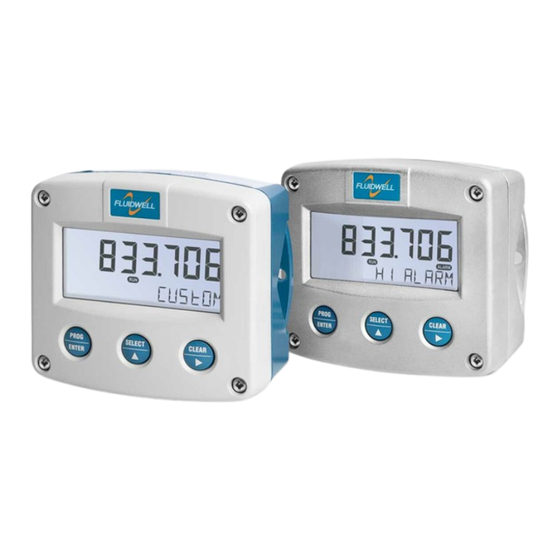
MULTI-PURPOSE MONITOR
with high / low alarms, analog and pulse outputs
Signal input sensor: (0)4-20 mA
Signal outputs: (0)4-20 mA ref. sensor signal or percentage
Alarm outputs: four level alarms
Options: Intrinsically safe, Modbus communication, and backlight
F-Series - Field mounted indicators for safe and hazardous areas.
More info: www.fluidwell.com/fseries
Advertisement
Table of Contents

Related Manuals for Fluidwell F190-A-OS


Summary of Contents for Fluidwell F190-A-OS
- Page 1 / low alarms, analog and pulse outputs Signal input sensor: (0)4-20 mA Signal outputs: (0)4-20 mA ref. sensor signal or percentage Alarm outputs: four level alarms Options: Intrinsically safe, Modbus communication, and backlight F-Series - Field mounted indicators for safe and hazardous areas. More info: www.fluidwell.com/fseries...
-
Page 2: Safety Instructions
Magnetic Compatibility). • Connect a proper grounding to the metal enclosure as indicated if the F190-A-OS has an incoming power or signal line which carries a hazardous live voltage. The Protective Earth (PE) wire may never be disconnected or removed. -
Page 3: About The Manual
This manual describes the standard unit as well as the available options. For additional information, please contact your supplier. A hazardous situation may occur if the F190-A-OS is not used for the purpose it was designed for or is used incorrectly. Please carefully note the information in this manual indicated by the pictograms: A "warning !"... -
Page 4: Table Of Contents
Page 4 TABLE OF CONTENTS SAFETY INSTRUCTIONS........................2 DISPOSAL OF ELECTRONIC WASTE ....................2 SAFETY RULES AND PRECAUTIONARY MEASURES ..............2 ABOUT THE MANUAL ........................3 WARRANTY AND TECHNICAL SUPPORT ..................3 TABLE OF CONTENTS ........................4 INTRODUCTION ........................6 System description ...................... - Page 5 Page 5 APPENDIX C COMMUNICATION VARIABLES ................39 APPENDIX D DECLARATION OF CONFORMITY ................. 44 INDEX OF THIS MANUAL........................45 LIST OF FIGURES IN THIS MANUAL ....................45 FW_F190-A-OS_M_v2201-01_EN.docx...
-
Page 6: Introduction
▪ transmitting possibilities with analog and communication outputs. Sensor input One sensor with a (0)4-20mA signal output can be connected to the F190-A-OS. To power the sensor, several options are available. Standard outputs ▪... - Page 7 Page 7 Configuration of the unit The F190-A-OS is designed for use in many types of applications. For that reason, a setup menu is available to program the F190-A-OS according to your specific requirements. The setup includes several important features, such as span, engineering units, signal selection, power management etc.
-
Page 8: Operational
Page 8 2 OPERATIONAL GENERAL INFORMATION This chapter describes the daily use of the F190-A-OS. This instruction is meant for users / operators. • This device may only be operated by persons who are authorized and trained by the operator of the facility. All instructions in this manual are to be observed. - Page 9 ▪ How to program the alarm thresholds The F190-A-OS can give an alarm message on the display. When set to on, at the same time, the digital outputs can give a signal for processing by an external device. Note that it is also possible to set or change the alarm thresholds from the setup menu.
-
Page 10: Configuration
Make sure that the unit is not being used for any application when altering the settings. 3.2.1 ENTERING SETUP-LEVEL Configuration of the F190-A-OS is done at SETUP-level, which can be reached at all times while the F190-A-OS remains fully operational. At SETUP-level the display will deactivate the indicator... -
Page 11: Programming Sequence
Page 11 Use the control panel to navigate through SETUP-level PROG-key When a function is selected, this key is used to start the programming sequence. When only a function group is selected (and no function), this key is used to scroll back a function group (e.g. -
Page 12: Returning To Operator-Level
In order to return to the operator level, press the PROG-key for three seconds. When no keys are pressed for 2 minutes, SETUP-level will be left automatically. CONFIGURATION SETTINGS All settings of the F190-A-OS can be set via the control panel. The following paragraphs give a detailed description of each setting. 3.3.1... -
Page 13: Menu 1 - Value
DATABITS 8 bits, 7 bits PARITY none, even. odd ADDRESS 1 - 247 TRANSMIT DELAY 0 – 255 ms OTHERS MODEL F190-A-OS SOFTWARE VERSION 03.05.xx SERIAL NO. nnnnnnn PASSWORD 0000 - 9999 TAG-NR 0000000 - 9999999 MENU 1 – VALUE 3.3.2... -
Page 14: Menu 2 - Alarm
Page 14 To enable the / (slash), select the /XXX entry at SETUP 1.2. When a different time unit is selected, the last 3 custom characters will be overwritten. Note: To clear the full set of characters: press CLEAR and SELECT simultaneously during 3 seconds. -
Page 15: Menu 3 - Hysteresis
Page 15 SETPOINT LOW- When low-low, low, high or high-high alarm monitoring is enabled at SETUP 2.3 to SETUP 2.6, the setpoints are set with these settings. SETPOINT LOW An alarm will be generated as long as the actual value is: SETPOINT HIGH LOW-LOW lower or equal to this setpoint. - Page 16 Page 16 OW ALARMS IGH ALARMS ISABLED This mode is used when only simple setpoints are required. An alarm is generated when the process value reaches the setpoint. The alarm is removed when the process value passes the setpoint again in the right direction. In this mode, the delay time is only active when an alarm is set, not when it is reset.
-
Page 17: Menu 4 - Display
BATTERY MODE The F190-A-OS has two modes: operational or shelf. After "shelf" has been selected, the F190-A-OS can be stored for several years; it will not process the sensor signal; the display is switched off but all settings are stored, also without additional battery. - Page 18 Page 18 FILTER The analog output signal of a sensor represents the actual process value. This signal is measured several times a second. The value measured is a "snap-shot" of the real value as it will be fluctuating. With the help of this digital filter a stable and accurate reading can be obtained while the filter level can be set to a desired value.
-
Page 19: Menu 7 - Analog Output
Page 19 3.3.8 MENU 7 - ANALOG OUTPUT A linear 4-20 mA signal output signal is generated that represents the process value. The relationship between sensor signal and the analog output is set with the following settings. ANALOG OUTPUT OUTPUT If the analog output is not used, select disable to minimize the power consumption. -
Page 20: Menu 8 - Relays
Page 20 0.7 sec 1.4 sec 2.2 sec 4.4 sec 1.4 sec 2.8 sec 4.5 sec 9.0 sec 2.1 sec 4 sec 7 sec 14 sec 3.5 sec 7 sec 11 sec 23 sec 5.2 sec 10 sec 17 sec 34 sec 6.9 sec 14 sec... -
Page 21: Menu 9 - Communication (Option)
Page 21 3.3.10 MENU 9 - COMMUNICATION (OPTION) The F190-A-OS can optionally be equipped with a communication interface using the Modbus protocol (Type CB/CH/CI/CT). Please consult Appendix C for a more detailed explanation of the protocol, data types and available registers. -
Page 22: Installation
• The F190-A-OS may only be operated by persons who are authorized and trained by the operator of the facility. All instructions in this manual are to be observed. •... -
Page 23: Handling The F-Series Enclosure
IDENTIFICATION The F1-Series can be supplied as suitable for Safe Area or Hazardous Area. Suitability for Intrinsic Safety is indicated in the model code by Type XI (e.g. F190-A-OS-XI). Identification label To identify your F1-Series device, all field mount enclosures have a weatherproof identification label placed on the outside of the unit. -
Page 24: Opening / Removing The Cover
Page 24 Terminal label Also on the inside, a terminal label is placed to indicate the location of the terminals and settings for the sensor supply configuration switches. Fig. 7: Identification – Example of F1-Series terminal label (safe area) Serial number and year of production The serial number can be reviewed on the identification label or in SETUP-menu Others. -
Page 25: Mechanical Installation
Page 25 MECHANICAL INSTALLATION DIMENSIONS – ALUMINUM AND STAINLESS STEEL ENCLOSURES 4.4.1 Fig. 8: Dimensions – Aluminum and stainless steel enclosures FW_F190-A-OS_M_v2201-01_EN.docx... -
Page 26: Dimensions - Non-Metallic Enclosures
Page 26 DIMENSIONS – NON-METALLIC ENCLOSURES 4.4.2 Fig. 9: Dimensions – Non-metallic enclosures FW_F190-A-OS_M_v2201-01_EN.docx... -
Page 27: Mounting
Page 27 4.4.3 MOUNTING The enclosure can be installed by itself or with the aid of a mounting plate in the configurations shown below. When the unit is installed on a wall or onto a meter, please use components and installation techniques that are suitable for the used materials. -
Page 28: Electrical Installation
Metal enclosure When the F190-A-OS is supplied with a metal enclosure (aluminum or stainless steel), the enclosure must be grounded in accordance with national and local electrical codes. -
Page 29: Field Wiring Connections
Within the United States all field wiring must conform to the National Electric Code, NFPA 70, Article 501-4(b). All field wiring enters the F190-A-OS through the bottom of the enclosure and connects to the circuit assembly inside the enclosure. Wiring is routed through cable glands. Please make sure to order the F190-A-OS with the correct drilling pattern and thread (metal) or hole (plastic) sizes. -
Page 30: Sensor Supply
Setting the sensor supply Risk of electrocution - High voltage! Make sure, all the leads to the terminals are disconnected from the F190-A-OS and NEVER connect mains power to the unit when the protection cover has been removed! To set the sensor supply, follow these instructions: 1. -
Page 31: Terminal Connectors Safe Area Applications - Type Xx / Xf
4.5: Electrical Installation and review paragraph 4.5.3 and 4.5.4 before applying any field or power supply wiring. For Intrinsically Safe applications (Type XI): read chapter 5. Following terminal connectors are available on the F190-A-OS when supplied with Type XX: Fig. 12: Overview of terminal connectors - Standard configuration and options 4.6.1... -
Page 32: Terminal 08-09: Analog Output
Page 32 4.6.2 TERMINAL 08-09: ANALOG OUTPUT An analog output signal proportional to the level is available (configuration: see Setup 7). Type AP A passive 4-20mA signal proportional to the level is available with this option. When a power supply is connected but the output is disabled, a 3.5mA signal will be generated. -
Page 33: Terminal 26-31: Type Cb / Ch / Ci - Communication (Option)
Page 33 4.6.4 TERMINAL 26-31: TYPE CB / CH / CI - COMMUNICATION (OPTION) Serial communications on hardware layers RS232 and RS485 are possible. Make sure that the hardware layer specific requirements are met to achieve reliable communication and read the Modbus communication protocol and Appendix C. -
Page 34: Maintenance
Repairs should only be carried out by the manufacturer or his authorized agent. Repair policy If you have any problem with your Fluidwell product and you wish to repair it, please follow the procedure below: a. Obtain a Return Material Authorization (RMA) from your supplier or distributor Together with the RMA, you need to complete a repair form to submit detailed information about the problem. -
Page 35: Appendix A Technical Specification
Page 35 APPENDIX A TECHNICAL SPECIFICATION General Display Type High intensity numeric and alphanumeric LCD, UV-resistant. Digits Seven 17mm (0.67") and eleven 8mm (0.31"). Various symbols and measuring units. Refresh rate User definable: 8 times/sec - 30 secs. Type ZB LCD with LED backlight. - Page 36 Page 36 Power supply Type PD 8-24V AC / 8-30V DC; Power consumption max. 5 Watt. Type PD-ZB 10-24V AC / 12-30V DC; Power consumption max. 5 Watt. Sensor supply Internal sensor supply External sensor supply Selection (see 4.5.5) 1.2 V DC / 3 V DC 8.2 V 12 V 24 V...
- Page 37 Page 37 Operational Operator functions Displayed information • Actual process value with set engineering unit • Percentage of full scale sensor output • Alarm status • Alarm thresholds Clear alarm Alarm outputs can be cleared in Operator mode (may be disabled) Set alarm thresholds May be disabled for Operator mode Process value...
-
Page 38: Appendix Bproblem Solving
Page 38 APPENDIX B PROBLEM SOLVING In this appendix, several problems are included that can occur when the F190-A-OS is going to be installed or while it is in operation. 5.2.1.1 Analog output does not function properly: Check: ▪ SETUP 7.1: is the function enabled? ▪... -
Page 39: Appendix C Communication Variables
Page 39 APPENDIX C COMMUNICATION VARIABLES General The product is fitted with the Modbus communication protocol and can be equipped with various physical interfaces like RS485 and RS232 (please see device datasheet for available options). The tables below show the various variables that can be accessed through the communication. Currently, the function codes supported are: •... - Page 40 Page 40 Setup variables REGISTER VARIABLE TYPE VALUE / REMARKS ADDRESS PROCESS VALUE REGISTERS [d] 48 40049 unit R/W uint16 Following preset units are available. [h] 0x030 Select custom to enter customer specific unit. 8=Kg 16=scf 24=mm 32=mbar 40=MH2O 48=no unit 1=NL 9=TON 17=p...
- Page 41 Page 41 [d] 237 40238 setpoint high-high R/W uint32 0...9999999 [h] 0x0ED Representation: -9999.999…9999999 depending on variable 48 and 253 [d] 253 40254 setpoint high-high sign R/W uint32 0 = + 1 = - [h] 0x0FD Sign for alarm value high-high (variable 237) [d] 1553 41554 reset point low-low...
- Page 42 Page 42 REGISTER VARIABLE TYPE VALUE / REMARKS ADDRESS SENSOR REGISTERS [d] 98 40099 formula uint16 0=interpol 1=SQRT [h] 0x062 [d] 99 40100 filter uint16 1...99 [h] 0x063 [d] 100 40101 cut-off uint16 0...999 [h] 0x064 Representation: 0.0 – 99.9% [d] 102 40103 calibrate low...
- Page 43 Page 43 REGISTER VARIABLE TYPE VALUE / REMARKS ADDRESS COMMUNICATION REGISTERS [d] 146 40147 Modbus mode uint16 0=ASCII 1=RTU 2=OFF [h] 0x092 [d] 144 40145 speed (baudrate) uint16 0=1200 2=4800 4=9600HP 6=38400 [h] 0x090 1=2400 3=9600 5=19200 7=57600 [d] 1271 41272 databits uint16 0=8bits...
-
Page 44: Appendix Ddeclaration Of Conformity
Page 44 APPENDIX D DECLARATION OF CONFORMITY eghel, ebruary 0 e, luidwell , declare under our sole responsibility that the 1 Series indicators are designed and will operate conform the following applicable uropean irectives and Harmonised Standards, when installed and operated according to the related manuals C irective 014 30 U 1000... -
Page 45: Index Of This Manual
Page 45 INDEX OF THIS MANUAL actual settings ..........46 Height .............8 Alarm ............. 9 Installation ........... 22 analog keys ..............8 cut-off value ..........19 Level ...............8 level min............ 19 Span ............14 tune / calibrate .......... 19 main-function ..........10 Analog output .......... - Page 46 Page 46 LIST OF CONFIGURATION SETTINGS SETTING DEFAULT DATE : DATE : 1 - VALUE Enter your settings here 1.1 unit 1.2 time unit ---- 1.3 customer unit ------- 1.4 decimals 0000000 1.5 span 0001600 1.6 decimals span 1.7 offset 2 - ALARM 2.1 input value...
- Page 47 Page 47 7 - ANALOG OUTPUT 7.1 output disabled 7.2 input value 7.3 min. value 4-mA 7.4 max. value 20mA 99999 7.5 cut off 0.0% 7.6 tune min - 4mA 0208 7.7 tune max - 20mA 6656 7.8 filter 01 (off) 8 –...
- Page 48 Fluidwell B.V. PO box 6 Voltaweg 23 Website: www.fluidwell.com 5460 AA Veghel 5466 AZ Veghel Find your nearest representative: www.fluidwell.com/representatives The Netherlands The Netherlands Fluidwell bv - © 2023 - FW_F190-A-OS_M_v2201-01_EN.docx...
Need help?
Do you have a question about the F190-A-OS and is the answer not in the manual?
Questions and answers