
Related Manuals for Grundfos FireSAFE+ Residential


Summary of Contents for Grundfos FireSAFE+ Residential
- Page 1 GRUNDFOS INSTRUCTIONS FireSAFE+ Residential Grundfos Firefighting Systems • Safety Instructions • Installation & Operating Instructions • CE & UKCA Declarations of Conformity P a g e...
-
Page 2: Table Of Contents
FireSAFE+ Residential Table of contents 1.0 Safety Instructions 2.0 When and how to use the FireSAFE+ 4.8 Break tanks and mains water connection Installation & Operating instructions 4.9 Installation - General requirements 2.1 Symbols used in this document 4.10 Installation and commissioning 2.2 Scope of these Instructions... -
Page 3: Safety Instructions
1.0 Safety Instructions Original Safety Instructions These safety instructions give an overview of the safety precautions to be considered in connection with any work on this product. Observe these safety instructions during handling, installation, operation, maintenance, service, and repair of this product. These safety instructions are an explanatory section, and all safety instructions will appear again in the relevant sections of the installation and operating instructions. - Page 4 Hazard: Electrical installation DANGER - Electric shock. Death or serious personal injury. If requiring repair consult Grundfos, details on back page. DANGER - Electric shock. Death or serious personal injury. - Check that the supply voltage and frequency correspond to the values stated on the nameplate.
- Page 5 DANGER - Electric shock Death or serious personal injury - If the control panel is cracked, perforated, or damaged, immediately isolate and contact Grundfos, details on back page, to arrange a repair/replacement. Hazard: Repair/Servicing the product DANGER - Electric shock Death or serious personal injury - Switch off the power supply to the unit.
-
Page 6: When And How To Use The Firesafe+ Installation & Operating Instructions
For Technical Information consult the FireSAFE+ Datasheet For CRi Pump specific information please consult the CRi Installation and Operating manual and datasheets. All the above documents are also available on the Grundfos Product Centre website at: www.grundfos.com/uk P a g e... -
Page 7: Product Identification
20/21/22/23/24 Approvals 2.4 Product Description The Grundfos FireSAFE+ (Safe Active Firefighting Equipment) range of pump packages are designed to comply with the requirements of the following: BS 9251:2021 - Fire sprinkler systems for domestic and residential occupancies. Code of practice EN 16925:2018 - Fixed firefighting systems. -
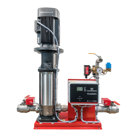
Page 8: Key Product Components
Pressure Switch LPCB Approved Drain Point Pump (Item 1) From the Grundfos high quality CRi pump range. See Pump data sheet for more info. Monitored Lockable Ball Valve (Item 2) Model 120 BS9251:2021 Fully Lockable Ball Valve wired back to controller to give fault output and visual indication. - Page 9 Test Line (Item 5) 1” BSP Test Line connection via a lockable ball valve. Cooling Line (Item 6) ½” BSP cooling line solenoid to activate at timed intervals to prevent the pump overheating during a closed valve condition. Non-Return Valve (Item 7) Non-Return Valve to prevent backflow into the pump and maintain system pressure.
-
Page 10: Installation And Operating Instructions
Original Installation and Operating Instructions 3.1 Sequence of Operation The Grundfos FireSAFE+ supplies water, usually from a storage tank, via a riser system within the building to a system of sprinkler heads. Should the pressure in the sprinkler system decay, through minor leakage, then the FireSAFE+ unit will detect this pressure drop, via inbuilt pressure switches and run the pump to re- pressurize the system (Jockey Mode). -
Page 11: Modes Of Operation
3.2 Modes of Operation The FireSAFE+ unit is specifically designed by Grundfos to assist system designers and installers with complying to the BS, EN and LPS standards, integrating key system signals, monitoring system conditions and to operate automatically. The FireSAFE+ controller has the following modes of Operation: o Jockey Mode - Pressure maintenance o Possible Fire Mode –... -
Page 12: Integration Of Signals
See section 3.5 3.3 Integration of Signals The FireSAFE+ unit is specifically designed with the ability to power and relay digital signals. The signals could be from any source, but Grundfos suggest the following important signals: o Flow Switch o Low Water Level The Flow switch device is the only device allowable under BS9251:2021 to determine the presence of a fire and to activate Fire Mode. -
Page 13: Mains Power Monitoring / Controller Internal Fuse Monitoring
3.4 Mains power monitoring / Controller internal fuse monitoring On the application of mains electrical power, the screen will become visible and the Power LED on the controller front panel illuminates and the Fault output moves to its healthy position. Upon failure of the mains power or the controller’s internal fuse the LED extinguishes, the Fault relay moves to its unhealthy position and after more than 2 hours without power the internal buzzer activates for 1 second every 30 minutes. -
Page 14: Button Press Functions
The controller front looks like the below and has a screen with buttons to perform various functions and scroll through the menu: 3.5 Button Press Functions 14 | P a g e... -
Page 15: Led Operation
3.6 LED Operation The controller will visually indicate the LED`s below and show faults with text on the screen shown in the example below: 15 | P a g e... -
Page 16: Programming Settings
• Remove USB memory stick device and replace the front cover Programming settings A text file called settings.txt, available from Grundfos, can be used to customize the unit values with the aid of a laptop before saving these to the USB device. Then performing the process described above. -
Page 17: Extracting Data (Downloading The Log Files)
3.8 Extracting Data (Downloading the Log files) Perform the above process. The USB memory device will now have 4 text files on. • Autotest Log (records results of all Autotest cycles, Auto or Manually initiated) • Fault (records the number and name of the fault and when it occurred) •... -
Page 18: Factory Settings
Device Name:-FireSAFE+ Resi Note – ; three lines each less than 21 characters The device name, Installer name, Installer Name:-Grundfos Pumps Ltd Installer Contact details are also ; three lines each less than 21 characters programmable up to 21 characters. -
Page 19: General Information
4.3 Warranty 1. The Grundfos warranty covers all defects within the FireSAFE+ originating from faulty workmanship and/or materials for a period of two years from the date of installation or thirty months from the date of dispatch from the factory, whichever is the shorter. -
Page 20: Frost Protection
Grundfos do not accept any responsibility for the use of FireSAFE+ unit to pump liquids which could be construed as being hazardous to health either by touch, ingestion or inhalation of fumes or gases given off by the liquid. -
Page 21: Break Tanks And Mains Water Connection
Ensure that the FireSAFE+ is positioned to allow access for examination and service. A minimum of 50cm should be left all around the FireSAFE+ unit. Adequate drainage facilities and protection from water damage in the immediate vicinity of the FireSAFE+ unit must be provided. The FireSAFE+ unit should not be installed in an unventilated small space, ensure adequate ventilation for the motor. -
Page 22: Installation And Commissioning Recommendations
4.10 Installation and commissioning recommendations We recommend that System Design, Installation and Maintenance of FireSAFE+ unit should only be completed by Engineers holding UKAS accredited certification (FIRAS/LPCB/IFCC). All electrical connections should be completed by a qualified and authorized electrician in accordance with the wiring diagram supplied within the control panel/this manual, the latest I.E.E. -
Page 23: Pressure Switch Settings
4.11 Pressure switch setting The FireSAFE+ Pressure switches are factory set at 1 bar below the Closed Valve Pressure of the pump. The factory setting may not be ideal for the site application, this can be changed to suit. The operating range of the pressure switches are 0.7-14 Bar and 2-42 Bar. An Insulated 5.5mm Nut Spinner should be used. -
Page 24: Electrical Connections
4.12 Electrical Connections Digital Input and Output terminals are suitable for max. 0.5mm cable. Digital Inputs are wetted with 12V DC Digital Output terminals are suitable for 5A max 24 | P a g e... -
Page 25: Installation Checklist
5.0 Installation checklist During the installation phase: DO NOT apply main power to the unit. DO NOT apply water to the unit. Step Done Activity Action/Check/Notes Fully read and study this manual. Report to supplier/customer Unpack, inspect for completeness and any damage. Do not use. -
Page 26: Commissioning Checklist
5.1 Commissioning checklist Before the commissioning phase starts ensure that the Installation checklist has been completed and check the state of the mains power and water supplied to the unit. Step Done Activity Action/Check/Notes Fully read and study this manual. Ensure that the installation location meets all the requirements in this manual and the latest applicable Standard. -
Page 27: System Verification Checklist
5.2 System Verification checklist Before the system is signed off and handed over to the customer the entire system needs to be performance verified. Step Done Activity Action/Check/Notes Fully read and study this manual. Inspect the installation, check everything in the installation and commissioning check list has been completed. -
Page 28: User Inspection
5.3 Operation After completion of the Installation, Commissioning and Verification checklists the FireSAFE+ unit is ready for operation. The FireSAFE+ unit is designed for automatic operation with the minimum of user input. The user does have the following option: 1 - Resetting of the weekly Auto test time to another more suitable time See section 3.5 Button Press Functions 2 - Silencing the internal buzzer for service alarms See section 3.5 Button Press Functions... -
Page 29: User Maintenance
5.5 User maintenance There are NO user serviceable parts in the FireSAFE+ unit. Maintenance must be completed by suitably qualified and competent personnel. 5.6 Service & Annual test/Inspection BS 9251:2021 recommends that the full fire protection system is tested and inspected every twelve months. -
Page 30: Service & Annual Test/Inspection Checklist
5.7 Service & Annual test/Inspection checklist Step Done Activity Action/Check/Notes Inspect the control panel for any LED Service/Fault indications. Refer to the fault-finding checklist. Clear all Service/Fault conditions first. TURN OFF - Follow a Safe Isolation Procedure before working on the unit. General inspection for loose fittings, pump fixings. -
Page 31: Technical Information
6.0 Technical Information 6.1 Product Range – Electrical Requirement 1 PHASE - 220-230V 1ph 50Hz POWER STARTING FULL LOAD PUMP SET Model STARTER TYPE (KW) CURRENT (Amps) CURRENT (Amps) PRODUCT CODE CRi 5-5 0.75 11.8 DIRECT ONLINE 92856363 CRi 5-12 2.20 46.2 DIRECT ONLINE... - Page 32 3 PHASE - 380-415V 3ph 50Hz FULL SOFT STANDARD SOFT-START STARTING POWER LOAD STARTER START PUMP SET PUMP SET Model CURRENT (KW) CURRENT TYPE CURRENT PRODUCT PRODUCT (Amps) (Amps) (Amps) CODE CODE DIRECT CRi 10-6 42.3 ONLINE 16.9 92856400 92856444 DIRECT CRi 10-7 58.0...
-
Page 33: Product Range - Pressures And Flows
6.2 Product Range – Pressures and Flows (consult Product Data sheets for Pump curves) 1 PHASE - 220-230V 1ph 50Hz Closed Valve Nominal Head Nominal Flow Model (Bar) (Bar) (L/Min) CRi 5-5 2.13 3.14 CRi 5-12 5.44 7.83 CRi 5-15 6.62 9.71 CRi 10-3... - Page 34 6.3 Product Range – Overall Dimensions and Weights 34 | P a g e...
- Page 35 1 PHASE - 220-230V 1ph 50Hz PIPEWORK PUMP SET SUCTION DELIVERY UNIT Model LENGTH WIDTH HEIGHT CENTRELINE PRODUCT DIAMETER DIAMETER WEIGHT HEIGHT CODE TYPE H (mm) CL (mm) (inches) (inches) (KG) (mm) (mm) (mm) (mm) CRi 5- 1120 1.25" 1.25" 92856363 CRi 5- 1120...
- Page 36 3 PHASE - 380-415V 3ph 50Hz SOFT- STANDARD PIPEWORK START SUCTION DELIVERY PUMP SET Model LENGTH WIDTH HEIGHT CENTRELINE UNIT WEIGHT PUMP SET DIAMETER DIAMETER PRODUCT HEIGHT PRODUCT CODE CODE SOFT SOFT START TYPE H (mm) CL (mm) (inches) (inches) START (mm) (mm)
-
Page 37: Spare Parts
7.0 Spare Parts Contact Grundfos Service for spare parts and advice regarding the FireSAFE+. 7.1 De-commissioning, Dismantling and Disposal The building will be without the Fire protection that the FireSAFE+ unit gives once decommissioned and an alternative measure to provide protection against fire should be considered. -
Page 38: Disposal
In case such waste collection services do not exist or cannot handle the materials used in the product, please deliver the product or any hazardous materials from it to your nearest Grundfos company or service workshop. Local and National environmental legislation must always be complied with. 38 |... -
Page 39: Fault Finding Checklist
8.0 Fault finding checklist Faults will be visually shown on controller and the light sequences below: Fault event Fault Detected and Remedy Screen Not Visible and No Power to the unit. Power LED not Check power to unit and protective devices. illuminated. - Page 40 3) Controller fuse blown. C) Check electrical supply to pump. 4) Faulty Controller. D) Contact your system 5) Power wiring to supplier/Grundfos Service for pump/controller. remedial action. Pump does not reach the duty point 1) Not enough water getting to the...
-
Page 41: History Log
9.0 History log Date Activity and notes Who / Contact details (Install, Commission, Verification, Inspection, Service, Fault, Recommendations) Installed date Commissioned date Commissioned settings Designed set pressure = Actual set pressure = Pressure Switch settings = Low water level Input used = Size of tank = Connected to Alarm panel = Connected to Siren/buzzer =... -
Page 42: Ukca Declaration Of Conformity
Poul Due Jensen Vej 7 DK-8850 Bjerringbro, Denmark. Manufacturer and person empowered to sign the UKCA Declaration of Conformity. If further details are required, please contact the Grundfos offices listed on the back page of these instructions. 42 | P a g e... -
Page 43: Eu Declaration Of Conformity
Poul Due Jensen Vej 7 DK-8850 Bjerringbro, Denmark. Manufacturer and person empowered to sign the EU Declaration of Conformity. If further details are required, please contact the Grundfos offices listed on the back page of these instructions. 43 | P a g e... - Page 44 Part no: 92941582 – Installation and Operating Manual – FireSAFE+ ECM: 1364420 dd 23/04/2023 Rev. 1.0 It is the continuing policy of Grundfos to develop and improve our products, and we reserve the right to amend prices and specification without prior notice.
Need help?
Do you have a question about the FireSAFE+ Residential and is the answer not in the manual?
Questions and answers