Table of Contents
Advertisement
Quick Links
Advertisement
Table of Contents

Related Manuals for Hoshizaki HNC-120AE-L


Summary of Contents for Hoshizaki HNC-120AE-L
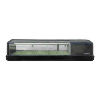
- Page 1 74NL-587 74NL-587 ISSUED: ISSUED: DEC. 20, 2001 DEC. 20, 2001 REVISED: REVISED: HOSHIZAKI HOSHIZAKI COUNTER SHOWCASE COUNTER SHOWCASE HNC-120AE-L/R HNC-120AE-L/R MODEL MODEL HNC-150AE-L/R HNC-150AE-L/R HNC-180AE-L/R HNC-180AE-L/R HNC-210AE-L/R HNC-210AE-L/R SERVICE MANUAL SERVICE MANUAL...
-
Page 2: Table Of Contents
3. OPERATING INSTRUCTIONS --------------------------------------------------------------------- ---------------------------------------------------------------------4 4 4. SPECIFICATIONS 4. SPECIFICATIONS ------------------------------------------------------------------------------------ ------------------------------------------------------------------------------------5 5 5. DIMENSIONS 5. DIMENSIONS ------------------------------------------------------------------------------------------ ------------------------------------------------------------------------------------------6 6 [a] HNC-120AE-L [a] HNC-120AE-L ------------------------------------------------------------------------------------- -------------------------------------------------------------------------------------6 6 [b] HNC-120AE-R [b] HNC-120AE-R ------------------------------------------------------------------------------------- -------------------------------------------------------------------------------------7 7 [c] HNC-150AE-L [c] HNC-150AE-L ------------------------------------------------------------------------------------- -------------------------------------------------------------------------------------8 8 [d] HNC-150AE-R... -
Page 3: Safety Instructions
1. SAFETY INSTRUCTIONS 1. SAFETY INSTRUCTIONS The following instructions contain important safety precautions and should be strictly observed. The following instructions contain important safety precautions and should be strictly observed. The terms used here are defined as follows: The terms used here are defined as follows: WARNING WARNING: : There is a possibility of death or serious injury for the service person and a third There is a possibility of death or serious injury for the service person and a third... - Page 4 5. Keep the following in mind when making electrical connections: 5. Keep the following in mind when making electrical connections: (1) Check for proper grounding connections, and repair if necessary to prevent electric (1) Check for proper grounding connections, and repair if necessary to prevent electric shocks.
-
Page 5: Model Name
2. MODEL NAME 2. MODEL NAME H H NC NC - - 120 120 A A E E - - R/L High Grade High Grade Unit Location Unit Location R: Unit on right R: Unit on right L: Unit on left L: Unit on left Counter Showcase Counter Showcase... -
Page 6: Operating Instructions
3. OPERATING INSTRUCTIONS IMPORTANT IMPORTANT Hoshizaki Counter Showcase is intended for temporary food display. Hoshizaki Counter Showcase is intended for temporary food display. Constructed with much glass, this showcase gives relatively insufficient heat Constructed with much glass, this showcase gives relatively insufficient heat insulation and poor cooling performance compared with refrigerators in general. -
Page 7: Specifications
4. SPECIFICATIONS MODEL HNC-120AE-L HNC-150AE-L HNC-180AE-L HNC-210AE-L AC SUPPLY VOLTAGE 1 Phase 220-240V 50Hz POWER SUPPLY CAPACITY 0.67kVA (2.8A) RATED AMPERAGE 1.1A STARTING AMPERAGE ELECTRIC CONSUMPTION 150W POWER FACTOR PULL DOWN TIME (10°C) Approx. 40 min. (Ambient Temp. 30°C, No Load) -
Page 8: Dimensions
5. DIMENSIONS 5. DIMENSIONS [a] HNC-120AE-L [a] HNC-120AE-L 74NL5870112 74NL5870112... -
Page 9: [B] Hnc-120Ae-R [B] Hnc-120Ae
[b] HNC-120AE-R [b] HNC-120AE-R 74NL5870112 74NL5870112... -
Page 10: [C] Hnc-150Ae-L [C] Hnc-150Ae
[c] HNC-150AE-L [c] HNC-150AE-L 74NL5870112 74NL5870112... -
Page 11: [D] Hnc-150Ae-R [D] Hnc-150Ae
[d] HNC-150AE-R [d] HNC-150AE-R 74NL5870112 74NL5870112... -
Page 12: [E] Hnc-180Ae-L [E] Hnc-180Ae-L
[e] HNC-180AE-L [e] HNC-180AE-L 74NL5870112 74NL5870112... -
Page 13: [F] Hnc-180Ae-R [F] Hnc-180Ae-R
[f] HNC-180AE-R [f] HNC-180AE-R 74NL5870112 74NL5870112... -
Page 14: [G] Hnc-210Ae-L [G] Hnc-210Ae-L
[g] HNC-210AE-L [g] HNC-210AE-L 74NL5870112 74NL5870112... -
Page 15: [H] Hnc-210Ae-R [H] Hnc-210Ae-R
[h] HNC-210AE-R [h] HNC-210AE-R 74NL5870112 74NL5870112... -
Page 16: Performance Data
6. PERFORMANCE DATA 6. PERFORMANCE DATA HNC-210AE HNC-210AE Test Conditions: Ambient Temperature 30°C, Frequency 50Hz, Standard Test Conditions: Ambient Temperature 30°C, Frequency 50Hz, Standard (°C) (°C) 60mm above food mount 20mm above food mount food mount surface (min) (min) Pull Down Time (from 30°C to 10°C) Pull Down Time (from 30°C to 10°C) 42 min 42 min... -
Page 17: Refrigeration Circuit
7. REFRIGERATION CIRCUIT 7. REFRIGERATION CIRCUIT Expansion Expansion Drier Drier Valve Valve Evaporator Evaporator Fan Motor Fan Motor (Upper) (Upper) Condenser Condenser Evaporator Evaporator (Lower) (Lower) Compressor Compressor Heat Exchange Heat Exchange Refrigerant: R134a Refrigerant: R134a 74NL5870112 74NL5870112... -
Page 18: Wiring Diagram
8. WIRING DIAGRAM 8. WIRING DIAGRAM Power Supply 1 phase 220 - 240V 50Hz Power Supply 1 phase 220 - 240V 50Hz GR/Y GR/Y (BR) (BR) (LBU) (LBU) (BK) (BK) (BK) (BK) Compressor Compressor Start Relay Start Relay Overload Relay Overload Relay Fan Motor Fan Motor... -
Page 19: Construction
9. CONSTRUCTION 9. CONSTRUCTION Sliding Door Sliding Door Food Mount Food Mount Center Frame Center Frame Holder - Evaporator Pipe Holder - Evaporator Pipe Top Cover Top Cover Evaporator Pipe Evaporator Pipe Side Frame Side Frame Front Glass Front Glass Cover - Unit Cover - Unit Unit... -
Page 20: Removal And Replacement
10. REMOVAL AND REPLACEMENT 10. REMOVAL AND REPLACEMENT CAUTION CAUTION 1. Be sure to unplug the showcase before removing or replacing the parts. 1. Be sure to unplug the showcase before removing or replacing the parts. 2. Handle the glass parts with care. 2. -
Page 21: [E] Side Frame [E] Side Frame
[e] SIDE FRAME [e] SIDE FRAME Remove the Sliding Door, Side Cover and Top Cover. Unbind the wiring on the Side Frame. Remove the Sliding Door, Side Cover and Top Cover. Unbind the wiring on the Side Frame. Remove the two screws securing the Top Frame and the top of the Side Frame. Lift the Side Remove the two screws securing the Top Frame and the top of the Side Frame. -
Page 22: [I] Unit [I] Unit
[i] UNIT [i] UNIT Remove the Sliding Door, Side Cover, Top Cover, Cover - Unit and Side Frame. Take off the Remove the Sliding Door, Side Cover, Top Cover, Cover - Unit and Side Frame. Take off the Compressor Terminal Cover and remove the Starter and Motor Protector. Uninsulate the Compressor Terminal Cover and remove the Starter and Motor Protector. -
Page 23: Refrigerant Service Information
11. REFRIGERANT SERVICE INFORMATION 11. REFRIGERANT SERVICE INFORMATION 1) Allowable Compressor Opening Time and Prevention of Lubricant Mixture [R134a] 1) Allowable Compressor Opening Time and Prevention of Lubricant Mixture [R134a] The compressor must not be opened more than 30 minutes in replacement or service. Do The compressor must not be opened more than 30 minutes in replacement or service. -
Page 24: Constant Pressure Expansion Valve And Refrigerant Charge 12. Constant Pressure Expansion Valve And Refrigerant Charge
8) Refrigerant Leak Check 8) Refrigerant Leak Check Refrigerant leaks can be detected by charging the unit with a little refrigerant, raising the Refrigerant leaks can be detected by charging the unit with a little refrigerant, raising the pressure with nitrogen and using an electric detector. Do not use air or oxygen instead of pressure with nitrogen and using an electric detector. -
Page 25: [D] Replacement [D] Replacement
[d] REPLACEMENT [d] REPLACEMENT WARNING WARNING Always protect the valve body by using a damp cloth to prevent the valve from Always protect the valve body by using a damp cloth to prevent the valve from overheating. Do not braze with the valve body exceeding 110°C. overheating. -
Page 26: Service Diagnosis
13. SERVICE DIAGNOSIS 13. SERVICE DIAGNOSIS PROBLEM PROBLEM POSSIBLE CAUSE POSSIBLE CAUSE REMEDY REMEDY [1] Showcase will not [1] Showcase will not 1. Ground Fault Cirucit Interrupter in 1. Ground Fault Cirucit Interrupter in 1. Turn ON. 1. Turn ON. start. - Page 27 UNIT A, STAFFORD PARK 18, TELFORD, SHROPSHIRE TF3 3DJ ENGLAND SHROPSHIRE TF3 3DJ ENGLAND PHONE: 01952-291777 PHONE: 01952-291777 HOSHIZAKI ELECTRIC CO., LTD. HOSHIZAKI ELECTRIC CO., LTD. 3-16 MINAMIYAKATA, SAKAE, TOYOAKE, 3-16 MINAMIYAKATA, SAKAE, TOYOAKE, AICHI 470-1194 JAPAN AICHI 470-1194 JAPAN...
Need help?
Do you have a question about the HNC-120AE-L and is the answer not in the manual?
Questions and answers