Table of Contents
Advertisement
Quick Links
Advertisement
Table of Contents

Related Manuals for Hoshizaki HW-600B


Summary of Contents for Hoshizaki HW-600B
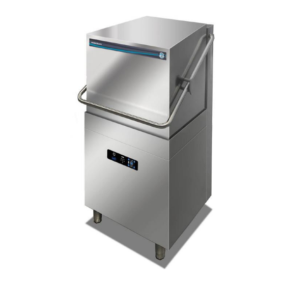
- Page 1 HW-600B/HW-600B3 PDRT SERVICE MANUAL...
-
Page 2: Table Of Contents
INDEX 1-Tecnical features and device dimensions------------------------ 2-Dishwasher Working Principle------------------------------------------ 3-General İnformation for Dishwasher -------------------------------- 3.a-İnternal Booster Tank---------------------------------------------- 3.b Washing tank -------------------------------------------------------- 4- Removal and Replacement of Components-------------------- 5.a Electrical Diagram HW 600B ---------------------------------- 5.b Electrical Diagram HW 600B3 ------------------------- 6. Cleaning and maintaince -------------------------------------------- 7- Quick user manual touch type--------------------------------------- 8- Accessing The Settinse Menu of Touch Panel-------------------... -
Page 3: 1-Tecnical Features And Device Dimensions
1-Tecnical features and device dimensions:... -
Page 6: 2-Dishwasher Working Principle
2-Dishwasher Working Principle : Water Path 1-Water inlet valve 2-Rinse pump 3-İnternal booster 4-Wash pump 5- Drain pump 6-Lower spray arm 7-Upper spray arm • The wash water is sprayed by the wash pump from the upper and lower wash spray arms into the wash compartment. •... -
Page 7: 3-General İnformation For Dishwasher
3-General İnformation for Dishwasher : Upper Rinse Spray arm Upper Wash Spray arm Lower Rinse Spray arm Lower Wash Spray arm Strainer Operation Panel Adjustable Leg... - Page 8 Spring Door Handle Door switch Wash tank Control box İnternal booster Rinse pump tank Washing tank Washing İnternal booster heater pump tank heater...
-
Page 9: A-İnternal Booster Tank
3.a-İnternal Booster Tank Water outlet Rinse aid enter Thermal protector Water inlet Heater o ring Heater Drain outlet Heater cover Thermistor (hot water temperature control) -
Page 10: Washing Tank
3.b Washing tank Thermistor (hot water temperature control) Thermal protector Air Trap Washing tank heater cover Overflow Pipe Pump Filter Wash Tank Heater Pressure Switch Sensing Hole... -
Page 11: 4- Removal And Replacement Of Components
4- Removal and Replacement of Components 1. This unit should be diagnosed and repaired only by qualified service personnel to reduce the risk of death, electric shock, serious injury, or fire. 2. Turn off the power supply before servicing. Lockout/Tagout to prevent the power from being turned back on inadvertently. - Page 12 4.b. Accessing the Control Box 1) Remove the front panel. 2) Pull out the control box slowly, then remove the PVC sheet to have access inside the control box. Note: Be careful not to tension the wires when pulling out the control box. 3) To replace, reverse the above procedure.
- Page 13 Touch Model Main card BREAKER 4,5 kw 3*25A Contactors...
- Page 14 4.c. Removal and Replacement of Internal Booster Tank 1) Turn off the power supply. Lockout/Tagout to prevent the power from being turned back on inadvertently. 2) Close the water supply line shut-off valve. 3) Drain the internal booster tank from the drain outlet (prepare a container) To avoid possible burns, allow the internal booster tank water temperature to fall below 40°C before draining.
- Page 15 6 ) Remove the rear panel. 7) Loosen the hose bands, and remove water supply overflow hoses. 8 ) Remove the heater , bi metal thermostat switch and thermistor wires. Screw Rear panel Screw Remove the screw at the rear of the unit .
- Page 16 10 ) and pull out the internal booster tank. Remove the screw at the front of the unit 11 ) To replace, reverse the above procedure. 12 ) Make a trial run, and check for water leaks 3.d. Removal and Replacement of Wash Pump Motor 1) Turn off the power supply.
- Page 17 6) Disconnect the washing pump wires. 7) Loosen the hose bands, and remove the suction and discharge hoses. 8 ) Remove the two nuts, and disconnect the wash pump motor. 9 ) To replace, reverse the above procedure. 10 ) Make a trial run, and check for water leaks. Nut (x2) Hose bands...
- Page 18 8) Remove the two nuts, and disconnect the wash pump motor. 9) To replace, reverse the above procedure. 10) Make a trial run, and check for water leaks Washing Pump tecnical info :...
- Page 19 3.e. Removal and Replacement of Rinse Pump Motor 1) Turn off the power supply. 2) Pull out the drain pipe to drain water from the wash tank. 3) Remove the front panel. 4) Pull the unit 1 m towards you. 5) Disconnect the rinse pump wires.
- Page 20 Rinsing Pump tecnical info :...
- Page 21 3.f. Removal and Replacement of Door 1) Open the door. Put some racks or other objects under the door to prevent it from closing. 2) Remove the bracket at the back of the door. 3) From inside the door, unscrew and remove the door handle side guide on both sides.
- Page 22 3.g.Removal and Replacement of Spring 1) Pull the unit 1 m towards you. 2) Remove the rear panel. 3) Remove the M10 flange nuts positioning the springs. 4) Remove the springs. 5) To replace, reverse the above procedure. 6) Check the door for proper movement. M10 flange Nut...
- Page 23 3.h. Removal and Replacement of Handle 1) Remove the door. See “3.F. Removal and Replacement of Door.” 2) Remove the springs. See “3.G. Removal and Replacement of Spring.” 3) Remove the handle cover on both sides. 4) Remove the 8 bolts securing the clamps. 5) Slide off the handle to the back.
- Page 24 I. U-Packing Installation Instructions Incorrect installation of the U-packings will cause water leaks.
-
Page 25: Electrical Diagram Hw 600B
5.a Electrical Diagram ( HW600B ) :... -
Page 26: Electrical Diagram Hw 600B3
5.b Electrical Diagram ( HW600B3) :... -
Page 27: Cleaning And Maintaince
6. CLEAN-UP AND MAINTENANCE 6.1 Periodical Maintenance and Clean-up Daily maintenance should be carried out by people informed about the safety instructions as following, after disconnecting power supply water connections. 6.1.1 Daily Maintenance: Daily maintenance should be carried by the user. In order to clean up the machine within the day following should be carried out periodically after the washing operation: 1. -
Page 28: 7- Quick User Manual Touch Type
7- Touch Quick user manual... -
Page 29: 8- Accessing The Settinse Menu Of Touch Panel
Accessing The Settinse Menu of Touch Panel Press and hold the settings icon for 3 sec. Changing Parameters You will see the pasword screen.Enter “3” for password. up and down buttons to enter “3”. You will see the pasword screen.Enter “3” for password. Hold 3 sec. - Page 30 Service Menu Chart By using the settings menu you can reach the below values. P01 Tank Temperature set : Tank temperature value can be adjusted from settings menu.The value can be between 4 °C and 100 °C. This setting is made separately for each program. P02 Boiler Temperature set : Boiler temperature value can be adjusted from settings menu.The value can be between 4 °C and 100 °C.
- Page 31 P03 Washing Time : Washing time can be adjusted from settings menu.The value can be between 1 second and 250 second. This setting is made separately for each program. P04 Rinse Time : Rinsing time can be adjusted from settings menu.The value can be between 1 second and 250 second.
- Page 32 P08 Getting detergent time - P09 Getting Rinse aid time : Detergent and rinse aid pumps are timed. It can be adjusted between 0 and 250 seconds. This means that the rinse aid / detergent is given to the system as much as the set value (seconds) you entered.
- Page 33 P16 Temperature unit : It changes the temperature unit of your machine, you can use either Fahrenheit or Celcius units. P17 Start bye door : If you set “0” this value ; To start washing programme you should touch the drop icon on control panel screen. If you set “1”...
Need help?
Do you have a question about the HW-600B and is the answer not in the manual?
Questions and answers