
Related Manuals for NCR VOYIX 7772-K475


Summary of Contents for NCR VOYIX 7772-K475
- Page 1 High Mount XL10 Customer Display Bracket, CX Kit Instructions 7772-K475 Issue B Confidential and proprietary information of NCR Corporation. Unauthorized use, reproduction and/or distribution is strictly prohibited...
-
Page 2: Copyright
NCR, therefore, reserves the right to change specifications without prior notice. All features, functions, and operations described herein may not be marketed by NCR in all parts of the world. In some instances, photographs are of equipment prototypes. Therefore, before using this document, consult with your NCR representative or NCR office for information that is applicable and current. -
Page 3: Table Of Contents
Table of Contents Copyright High Mount XL10 Customer Display Bracket, CX Kit Contents Installation Procedure Installing the Back Neck Cover Confidential and proprietary information of NCR Corporation. Unauthorized use, reproduction and/or distribution is strictly prohibited. - Page 4 Revision Record Issue Date Remarks Dec 2021 First Issue Aug 2023 Added 497-0523787 Confidential and proprietary information of NCR Corporation. Unauthorized use, reproduction and/or distribution is strictly prohibited.
-
Page 5: High Mount Xl10 Customer Display Bracket, Cx
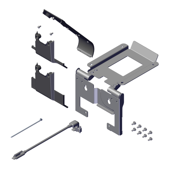
External Tooth Lock Washer, Black, Zinc 497-0529413 Cable, USBC, 10” Customer Display, 506mm 497-0531570 Cable Cover, Cast, Black 497-0531574 4:3 Cable Cover, Cast 497-0480152 Screw, M3x6mm, Machine, Phillips, Pan Head Confidential and proprietary information of NCR Corporation. Unauthorized use, reproduction and/or distribution is strictly prohibited. -
Page 6: Installation Procedure
Always use a soft material (cloth, foam) to protect the display screen when placing the terminal face down. 2. Remove the Cable Cover. a. Remove the two (2) screws that secure the Cable Cover to the Back Cover. Confidential and proprietary information of NCR Corporation. Unauthorized use, reproduction and/or distribution is strictly prohibited. - Page 7 3. Connect the USB-C Cable to the CX7 Display and tighten the thumbscrew. Note For clarity, the Neck is not shown in the illustration below and in the succeeding illustrations. Confidential and proprietary information of NCR Corporation. Unauthorized use, reproduction and/or distribution is strictly prohibited.
- Page 8 Secure the Cable Cover with two (2) screws. 5. Partially install two (2) screws on the back of the CX7 Display in the location shown. Confidential and proprietary information of NCR Corporation. Unauthorized use, reproduction and/or distribution is strictly prohibited.
- Page 9 6. Hook the Bracket on the partially installed screws. Ensure the Cable is routed as shown. 7. Tighten the two (2) partially installed screws and install two (2) screws on the bottom of the Bracket. Confidential and proprietary information of NCR Corporation. Unauthorized use, reproduction and/or distribution is strictly prohibited.
- Page 10 8. Connect the other end of the Cable to the back of the XL10 Customer Display and tighten the thumbscrew. 9. Secure the Cable on the side of the bridge lance using a cable tie as shown. Confidential and proprietary information of NCR Corporation. Unauthorized use, reproduction and/or distribution is strictly prohibited.
- Page 11 10. Install the XL10 Customer Display on the Bracket (4 screws). Ensure the Cable is routed through the gap in the Bracket as shown. 11. Pivot the XL10 Customer Display into position. Confidential and proprietary information of NCR Corporation. Unauthorized use, reproduction and/or distribution is strictly prohibited.
-
Page 12: Installing The Back Neck Cover
The Base Rear Foot serves to manage the cables and hold the bottom of the Neck Cover in place. 3. Attach the Front Neck Cover to the Neck. Confidential and proprietary information of NCR Corporation. Unauthorized use, reproduction and/or distribution is strictly prohibited. - Page 13 4. Secure the Front Neck Cover to the Neck with two (2) screws. Use the appropriate screws: flat head screws for Base without Integrated Power Supply thumbscrews for Base with Integrated Power Supply Confidential and proprietary information of NCR Corporation. Unauthorized use, reproduction and/or distribution is strictly prohibited.
Need help?
Do you have a question about the VOYIX 7772-K475 and is the answer not in the manual?
Questions and answers