Advertisement
Quick Links
Advertisement

Related Manuals for Studio Technologies 5205


Summary of Contents for Studio Technologies 5205
- Page 1 Mic/Line to Dante Interface User Guide Issue 5, December 2023 This User Guide is applicable for serial numbers M5205-02001 and later with application firmware 3.2 and later. Copyright © 2023 by Studio Technologies, Inc., all rights reserved studio-tech.com 50280-1223, Issue 5...
- Page 2 This page intentionally left blank.
-
Page 3: Table Of Contents
Table of Contents Revision History................4 Introduction ................... 5 Getting Started ................7 Connections.................. 7 Dante Configuration..............8 Operation ..................8 Technical Notes ................10 Specifications ................13 Model 5205 User Guide Issue 5, December 2023 Studio Technologies, Inc. Page 3... -
Page 4: Revision History
• Documents that the P48 status LED will no longer necessarily be blue in color. Issue 2, August 2017: • Documents that the unit now supports the STcontroller software application. Issue 1, August 2015: • Initial release. Issue 5, December 2023 Model 5205 User Guide Page 4 Studio Technologies, Inc. -
Page 5: Introduction
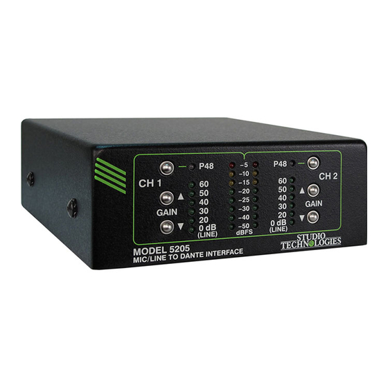
AV installations, and post-production condenser microphones P48 phantom power can be facilities. independently selected as required for each channel. Figure 1. Model 5205 Mic/Line to Dante Interface front and rear views Model 5205 User Guide Issue 5, December 2023 Studio Technologies, Inc. - Page 6 The audio signals, now in the digital domain, are con- Audio data is sent from the Model 5205 using the nected to the Dante interface section where they are Dante Audio-over-Ethernet media networking tech- packetized and prepared for transport over Ethernet.
-
Page 7: Getting Started
802.3af-compatible it should function correctly. equipment rack. Hook-and-loop (“Velcro”) tape can Midspan units are available from a variety of sources, be used to secure the Model 5205 units to the shelf. including Studio Technologies. A set of mounting brackets is available to allow a... -
Page 8: Dante Configuration
DDM documen- Initial Operation tation for details on what Model 5205 and related The Model 5205 will begin to function as soon as parameters may have to be configured. a Power-over-Ethernet (PoE) power source is con- The two transmitter (output) channels associated with nected. - Page 9 Dante interface and associated network. The connected. SYS LED will light red upon Model 5205 power up to As expected, a signal connected to the channel 1 indicate that the Dante interface is not ready. After...
-
Page 10: Technical Notes
A USB type A connector and associated status LED computer users to view and adjust the Model 5205’s is located on the back panel of the Model 5205. This data interface is used only for updating the unit’s ap- preamplifier gain and P48 phantom power on/off plication firmware. - Page 11 IP address is to create a “mini” version numbering scheme. LAN with a personal computer connected directly to the Model 5205. Then by using the appropriate ARP Application Firmware Update command the required “clues” can be obtained.
- Page 12 The flash drive doesn’t have to be empty (blank) firmware. but must be in the personal-computer-standard FAT32 7. At this time the Model 5205 is functioning with the format. Save the new firmware file in the root folder newly loaded application firmware and the USB with a name of m5205.bin.
-
Page 13: Specifications
EIN: –123 dBu, 22 kHz bandwidth, 60 dB gain, 150 ohm source resistance IMD (SMPTE): <0.002%, 60 Hz/7 kHz, 4:1, Specifications and information contained in this –20 dBFS User Guide subject to change without notice. Model 5205 User Guide Issue 5, December 2023 Studio Technologies, Inc. Page 13...
Need help?
Do you have a question about the 5205 and is the answer not in the manual?
Questions and answers