Table of Contents
Advertisement
Quick Links
Advertisement
Table of Contents

Related Manuals for Studio Technologies 40


Summary of Contents for Studio Technologies 40
-
Page 1: User Guide
Model 40 Central Controller and Related Components User Guide Issue 1, July 1994 © 1994 by Studio Technologies, Inc., all rights reserved 5520 West Touhy Avenue Skokie, Illinois 60077 U.S.A. Telephone (847) 676-9177 Fax (847) 982-0747 www.studio-tech.com 50065-794, Issue 1... -
Page 2: Table Of Contents
Table of Contents Introduction ..............5 What This User Guide Covers ........ 5 System Overview ............ 5 Model 40 Central Controller ........5 Model 35 Talent Amplifier ........7 Model 38 Talent Amplifier ........7 Installation ..............9 Configuration ............... 13 Operation .............. - Page 3 This page intentionally left blank. Issue 1, July 1994 Model 40 User Guide Page 4 Studio Technologies, Inc.
-
Page 4: Introduction
Locating talent amplifiers over 500 feet schematic diagrams. (164m) away from a Model 40 is perfectly acceptable. System Overview The underlying concept of a StudioComm Model 40 Central Controller... - Page 5 StudioComm talent analog source can be connected to the amplifier modules. The physical output Model 40’s line inputs. The inputs accept of each group is a 3-pin male XLR-type balanced or unbalanced signals, with an connector that provides power and left acceptable input level range of –10dBV to...
-
Page 6: Model 35 Talent Amplifier
LED. A single microphone- combined with the stereo cue mix supplied type cable links the Model 35 with the by the Model 40. This allows the Model 38 Model 40 Central Controller. user to create an individual headphone... - Page 7 “more me” in the phones! Like the Model 35, the Model 38 is linked with a Model 40 Central Controller by a single cable. Model 38 Front Panel LEVEL LEVEL STEREO STEREO MONO (L)
-
Page 8: Installation
–10dBV to +10dBu. The input standard 19-inch (48.3cm) equipment impedance is 50K ohms so that compatibil- rack. It is desirable to locate the Model 40 ity with virtually every source is assured. to allow easy access to both the front and the back panels. - Page 9 Example Installation Recorder/Reproducer Model 40 Central Controller Model 35 Talent Amplifiers Model 38 Talent Amplifier Output Group 1 Output Group 2 Total of eight headphones per group Issue 1, July 1994 Model 40 User Guide Page 10 Studio Technologies, Inc.
- Page 10 The simplest installation would use micro- inputs, while giving the ability to phone cables to connect the Model 40 to quickly “patch in” a stereo source. the first talent amplifier in each group; the...
- Page 11 AC Mains Power As soon as mains power is applied, the Model 40’s power present LED will light. The Model 40 is internally configured to The power present LEDs on the talent operate from either 100, 120, or 220/240V, amplifiers will also light.
-
Page 12: Configuration
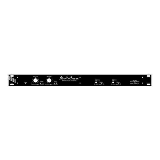
Model 40 Central Controller example, the output of a console is The Model 40’s front panel contains seven connected to the input of the Model 40, LEDs, two controls, and two switches. the console output should be adjusted so that the meters read 0dB or 100%. -
Page 13: Talent Amplifiers
The Signal Present LEDs will light when- be lit whenever the Model 38 is connected ever a signal of “reasonable” level is to an operating Model 40. You can plug in connected to its respective input. one or two pairs of headphones with a total impedance of 75 ohms or greater. -
Page 14: Troubleshooting
+20Vdc between pins 1 and 2 of the short circuit condition is located. The their input connector. The Model 40’s Model 40 will not be damaged if the Over talent amplifier output voltage across pins Current LED is flashing so you should use... - Page 15 It seems that some plug manufacturers don’t bother to make The Model 40 is designed to interface with the tip comply with the standard. Why is audio signals that have nominal signal this relevant to you? Because the phone levels of –10dBV to +10dBu.
-
Page 16: Circuit Description
Removing the cover or the Model 38 Talent Amplifiers depends on back panel from the Model 40 Central the proper setting of the Model 40’s input Controller exposes personnel to hazard- level controls. The headphone volume is ous voltages. Repairs or modifications... - Page 17 Using this scheme, the Model 40 will Interesting technical note department: operate reliably, even with wide swings notice that a diode is connected from the...
- Page 18 DC voltages Analog Circuitry of unknown polarity to be received on a The Model 40 takes advantage of an line input. The wiper of the pot is con- excellent series of audio-specific inte- nected to one section of op amp config- grated circuits from Analog Devices.
- Page 19 +26Vdc from +V UNREG. The provided by a talent amplifier output group regulator has inherent thermal protection from the Model 40 Central Controller. The so that an over-current condition will not major components of the Model 35 are the damage the circuitry.
- Page 20 Two identical amplifier circuits provide the phones to be driven with a mix of audio left and right headphone outputs. The from the Model 40 Central Controller, circuits are designed to produce a maxi- along with another signal that we refer to mum voltage swing, rather than to source as the talent signal.
- Page 21 30dB when set to the line position. described. Signal diodes protect the inputs of the Cue mix audio (audio from the Model 40) op amp from destruction due to an enters the amplifier via an electrolytic over-voltage condition. Compensation...
-
Page 22: Specifications
Specifications audio at –10dBu on pin 2, and right channel audio at –10dBu on pin 3. Maximum output current 200mA (nominal) Model 40 Central Controller Frequency Response, Distortion (THD+N), Mounting S/N Ratio: refer to Model 35 and Model 38 One space in a standard 19-inch (48.3cm) rack... - Page 23 Model 35 Talent Amplifier Connectors Cue Mix Input (from Model 40): 3-pin XLR-type, Mounting female (Neutrik) Desktop. Provision for stand mounting available as option. Cue Mix Input Loop Thru: 3-pin XLR-type male, connected in parallel with input connector (Neutrik) Power Requirements...
-
Page 24: Appendix
Appendix Block Diagrams The following block diagrams are contained in this guide: Model 40 Central Controller Model 35/Model 38 Talent Amplifiers Model 40 User Guide Issue 1, July 1994 Studio Technologies, Inc. Page 25... - Page 25 This page intentionally left blank. Issue 1, July 1994 Model 40 User Guide Page 26 Studio Technologies, Inc.
Need help?
Do you have a question about the 40 and is the answer not in the manual?
Questions and answers