
Related Manuals for Studio Technologies 43


Summary of Contents for Studio Technologies 43
-
Page 1: User Guide
User Guide Issue 1, July 2004 This User Guide is applicable for serial numbers: M43-00151 and later Copyright © 2004 by Studio Technologies, Inc., all rights reserved www.studio-tech.com 50020-0704, Issue 1... -
Page 2: Table Of Contents
Table of Contents Introduction ..............5 Setup ................7 Operation ..............10 Troubleshooting ............10 Technical Notes ............. 12 Specifications ..............14 Appendix A ..............16 Block Diagram Model 43 User Guide Issue 1, July 2004 Studio Technologies, Inc. Page 3... - Page 3 This page intentionally left blank. Issue 1, July 2004 Model 43 User Guide Page 4 Studio Technologies, Inc.
-
Page 4: Introduction
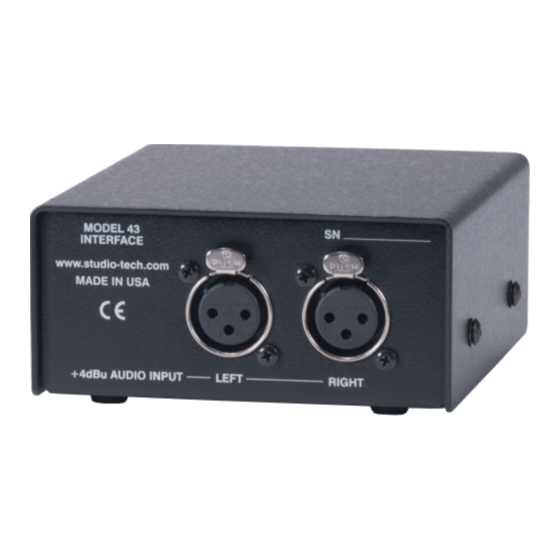
The Model 43 is a unique and ver- View showing left and right audio inputs satile product, providing the resources to easily create a high-performance “wet” IFB There may be persons not familiar with circuit in a compact, easy-to-use package. - Page 5 200 milliamperes. A major level of +4 dBu, and are compatible with strength of the Model 43 is the IFB circuit’s balanced or unbalanced sources. In on- ability to effectively deliver DC power over air television broadcast applications the a variety of conditions.
-
Page 6: Setup
DC voltage. This output voltage of stereo headphones to be supported. The stability is the key—whether drawing 50, Model 43’s IFB circuit will support up to six 100, or 200 milliamperes, the output will Model 35 Talent Amplifiers. -
Page 7: Audio Input Connections
+4 dBu As one would expect, the specific location and are compatible with balanced or un- selected for the Model 43 will dictate the balanced sources. With balanced sources length of cable that will be needed to link the mating connectors (males) should be the unit with the connected device(s). - Page 8 It is recommended that the focus be on a second channel of unbalanced audio. using excellent twisted-pair cable, rather With the Model 43, the DC power supplied than worrying about whether or not it is on pin 2 is 30 volts nominal with a maxi- shielded.
-
Page 9: Operation
As soon as 24 volts DC is applied, impact the DC power supplied by the the Model 43’s power present LED will Model 43. There’s no way to get around the light. The unit is now fully functional. fact that some DC voltage will be dropped by the interconnecting cable. - Page 10 The Model 72 the 3-pin female XLR-type connector that should prove to be very useful, both dur- is plugged into the Model 43. If after a few ing initial Model 43 installation and routine seconds the LED again lights, carefully system testing.
-
Page 11: Technical Notes
If possible, leaving a 10 or 20% reserve difference between the voltage supplied margin is a good practice. by the Model 43 (30 volts) and the volt- age required by the Model 220 (24 volts) allows a 6 volt maximum drop over the Technical Notes interconnecting cable. - Page 12 43’s strengths is its ability to very effec- the Model 43’s IFB circuit with an IFB user tively deliver energy to the connected IFB device. One pair carried the pin 2 (DC with user device(s).
- Page 13 The results were worth the effort. The performance differences are quite interesting. 4010 Model 43 Current (mA) Figure 1. IFB Circuit Voltage-Current Curves for RTS 4000-Series and Model 43 Interface Issue 1, July 2004 Model 43 User Guide Page 14 Studio Technologies, Inc.
-
Page 14: Specifications
Maximum Audio Output Level: Pin 2: +9 dBu with +23 dBu on audio input Pin 3: +14 dBu with +28 dBu on audio input DC Current Output: 200 mA maximum Model 43 User Guide Issue 1, July 2004 Studio Technologies, Inc. Page 15... - Page 15 Appendix A Interfacing Riedel Artist™ Matrix Intercom Systems with the Model 43 Interface Information courtesy of Riedel Communications Inc. Issue 1, July 2004 Model 43 User Guide Page 16 Studio Technologies, Inc.
Need help?
Do you have a question about the 43 and is the answer not in the manual?
Questions and answers