Table of Contents
Advertisement
Quick Links
Model 545DR
Intercom Interface
User Guide
Issue 1, May 2022
This User Guide is applicable for serial numbers
M545DR-00151 and later with Application Firmware 1.00 and later
and STcontroller application version 3.08.00 and later.
Copyright © 2022 by Studio Technologies, Inc., all rights reserved
studio-tech.com
50725-0522, Issue 1
Advertisement
Table of Contents

Related Manuals for Studio Technologies 545DR


Summary of Contents for Studio Technologies 545DR
- Page 1 Issue 1, May 2022 This User Guide is applicable for serial numbers M545DR-00151 and later with Application Firmware 1.00 and later and STcontroller application version 3.08.00 and later. Copyright © 2022 by Studio Technologies, Inc., all rights reserved studio-tech.com 50725-0522, Issue 1...
- Page 2 This page intentionally left blank.
-
Page 3: Table Of Contents
Table of Contents Revision History ..........................4 Introduction............................5 Getting Started ..........................8 Dante Configuration .......................... 12 Model 545DR Configuration ......................14 Operation............................16 Technical Notes ..........................21 Specifications ............................ 24 Appendix A–STcontroller Default Configuration Values ..............26 Appendix B– Graphical Description of the Installation Kit for Panel-Cutout or Surface-Mounting Use (Order Code RMBK-10) ...................... -
Page 4: Revision History
Model 545DR INTERCOM INTERFACE Revision History Issue 1, May 2022: • Initial release. Issue 1, May 2022 Model 545DR User Guide Page 4 Studio Technologies, Inc. -
Page 5: Introduction
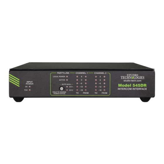
Versions supported devices such as matrix intercom systems, of STcontroller are available that are compatible with PHOTO COMING SOON Figure 1. Model 545DR Intercom Interface front and back views Model 545DR User Guide Issue 1, May 2022 Studio Technologies, Inc. - Page 6 Optional mounting kits allow 2-channel party-line intercom circuit with one or one or two Model 545DR units to be mounted in one two single-channel party-line intercom circuits. This space (1U) of a standard 19-inch rack enclosure.
- Page 7 Audio Meters troller application. This makes it simple to select The Model 545DR contains two sets of 5-segment the way in which a Model 545DR fits into a specific LED level meters. Each set of two meters displays the application.
-
Page 8: Getting Started
Rack-mounting option kits are available that allow one Model 545DR units. It also allows a Model 545DR to or two Model 545DR units to be mounted in one space send and receive call light status signals with an in- (1U) of a standard 19-inch rack enclosure. - Page 9 Locating the Model 545DR sure. Orient the standard-length bracket such that its Where to locate a Model 545DR will depend on be- front is parallel to the Model 545DR’s front panel. The ing able to access the associated party-line circuit or screws will mate with the threaded fasteners that can wiring provided for the desired user devices.
- Page 10 The screws will mate with the threaded fasten- enclosure, use a #2 Phillips screwdriver and two ers that can be seen on the side of the Model 545DR’s 6-32 machine screws to attach the standard-length enclosure, near the front of the unit. Using two more...
- Page 11 12 volts DC, correct operation will take place are removed using a #1 Phillips screwdriver. Store the over a 10 to 18 volts DC range. The Model 545DR four machine screws and four “bump on” protectors requires a maximum current of 1.0 amperes for cor- for possible later use.
-
Page 12: Dante Configuration
Dante interface is compatible with the Dante Domain For convenience, the party-line intercom circuit and/or Manager (DDM) software application. user devices can connect to the Model 545DR by way Audio Routing of the male and female 3-pin XLR connectors that are Two Dante transmitter (output) channels on associ- located on the unit’s back panel. - Page 13 Channel 2 channel on the other unit. Address The other typical application will have one Model By default, the Model 545DR’s Dante IP address and 545DR connected to an existing party-line inter- related network parameters will be determined auto- com circuit or a set of user devices. Then the unit’s...
-
Page 14: Model 545Dr Configuration
If required, download and install STcontroller onto a designated personal computer. This personal computer must be on the same local area network (LAN) and subnet as the one or more Model 545DR units that are to be configured. Immediately after starting STcontroller the application will locate all the Studio Technologies’... - Page 15 Model 545DR INTERCOM INTERFACE ACTIVE on the unit’s front panel will light green, the When the Model 545DR has been set to not provide PL Active status icon on the STcontroller’s menu local power the PL Active Detection function works page will show green, and the two Dante transmitter in a slightly different way.
-
Page 16: Operation
(A 12 volts DC power source is not includ- with one pushbutton switch, two input power status ed with the Model 545DR. One can be purchased as an LEDs, two party-line intercom circuit status LEDs, two option.) The Dante receiver (input) and transmitter (out- auto null LEDs, and four 5-segment LED level meters. - Page 17 Model 545DR and the signal level may be prudent. Typical operation associated party-line user devices.
- Page 18 (drop) by about 6 dB. In addition, auto null circuits, beltpacks can be directly supported. The LOCAL such as provided by the Model 545DR, will not be POWER status LED will light green when this mode able to obtain good separation (nulling) performance.
- Page 19 According to this figure, one or two of these units can interface’s 3-pin XLR connectors, will light to indicate be connected to a Model 545DR. All newer versions of that the output is active. The PL Active virtual LED the BP-325 use surface-mount component technology in STcontroller will light green.
- Page 20 Normally, the nulling process is performed at the time called the PL Active Detection function and disabling of initial Model 545DR configuration but there’s no it can be appropriate for special applications. Refer reason why it can’t be initiated any time one desires.
-
Page 21: Technical Notes
Model 545DR INTERCOM INTERFACE Technical Notes Call Light Support The Model 545DR provides a call light support func- IP Address Assignment tion, allowing high-frequency signals associated with By default, the Model 545DR’s Dante-associated the call light functions on Model 5454DR-connected Ethernet interface will attempt to automatically obtain user devices to work together. - Page 22 FAT32 Ethernet traffic enabling IGMP snooping can be valu- format. The USB interface in the Model 545DR is able. (In this case, ensure that support for PTP timing compatible with USB 2.0-, USB 3.0-, and USB messages is still available.) These protocols can be...
- Page 23 The latter allows the Dante Updater software application that is included with Dante Controller to 4. After a few seconds the Model 545DR will run a automatically query and, if required, update the Model “boot loader” program that will automatically load 545DR’s Dante interface.
-
Page 24: Specifications
Compatibility: 2-channel PL intercom systems such Humidity: 0 to 95%, non-condensing as those offered by RTS ® Altitude: not characterized Power Source: 29 volts DC, 240 mA maximum, on XLR pin 2 Issue 1, May 2022 Model 545DR User Guide Page 24 Studio Technologies, Inc. - Page 25 (1U) of a standard 19-inch rack RMBK-13 allows one unit to be mounted in the center of one space (1U) of a standard 19-inch rack DC Power Supply Option: Studio Technologies’ PS-DC-02 (100-240 V, 50/60 Hz, input; 12 volts DC, 1.5 A, output), purchased separately Specifications and information contained in this User Guide subject to change without notice.
-
Page 26: Appendix A-Stcontroller Default Configuration Values
Model 545DR INTERCOM INTERFACE Appendix A–STcontroller Default Configuration Values System – Call Light Support: On System – PL Active Detection: On Issue 1, May 2022 Model 545DR User Guide Page 26 Studio Technologies, Inc. -
Page 27: Appendix B- Graphical Description Of The Installation Kit For Panel-Cutout Or Surface-Mounting Use (Order Code Rmbk-10)
Appendix B–Graphical Description of the Installation Kit for Panel Cutout or Surface-Mounting Use (Order Code: RMBK-10) This installation kit is used for mounting one Model 545DR unit into a panel cutout or flat surface. Model 545DR User Guide Issue 1, May 2022 Studio Technologies, Inc. -
Page 28: Appendix C-Graphical Description Of Left- Or Right-Side Rack-Mount Installation Kit For One "1/2- Rack" Unit (Order Code Rmbk-11)
Installation Kit for One “1/2-Rack” Unit (Order Code: RMBK-11) This installation kit is used for mounting one Model 545DR unit into one space (1U) of a 19-inch equipment rack. Unit will be located on the left- or right-side of the 1U opening. -
Page 29: Appendix D-Graphical Description Of Rack-Mount Installation Kit For Two "1/2- Rack" Units (Order Code Rmbk-12)
Two “1/2-Rack” Units (Order Code: RMBK-12) This installation kit can be used to mount two Model 545DR units or one Model 545DR unit and another product that is compatible with the RMBK-12 (such as the Studio Technologies’ Model 5421 Dante Intercom Audio Engine) into one space (1U) of a 19-inch equipment rack. -
Page 30: Appendix E-Graphical Description Of Center Rack-Mount Installation Kit For One "1/2- Rack" Unit (Order Code Rmbk-13)
One “1/2-Rack” Unit (Order Code: RMBK-13) This installation kit is used for mounting one Model 545DR unit into one space (1U) of a 19-inch equipment rack. Unit will be located in the center of the 1U opening. Issue 1, May 2022...
Need help?
Do you have a question about the 545DR and is the answer not in the manual?
Questions and answers