Table of Contents
Advertisement
Quick Links
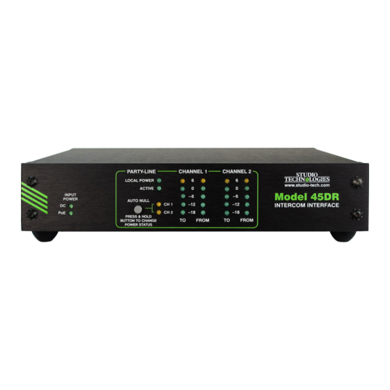
Model 45DR
Dante™ to 2-Channel
Party-Line Intercom Interface
User Guide
Issue 2, January 2015
This User Guide is applicable for serial numbers
M45DR-00151 and later with application firmware 2.1 and later
Copyright © 2015 by Studio Technologies, Inc., all rights reserved
www.studio-tech.com
50015-0115, Issue 2
Advertisement
Table of Contents

Related Manuals for Studio Technologies 45DR


Summary of Contents for Studio Technologies 45DR
-
Page 1: User Guide
Party-Line Intercom Interface User Guide Issue 2, January 2015 This User Guide is applicable for serial numbers M45DR-00151 and later with application firmware 2.1 and later Copyright © 2015 by Studio Technologies, Inc., all rights reserved www.studio-tech.com 50015-0115, Issue 2... - Page 2 This page intentionally left blank.
-
Page 3: Table Of Contents
Table of Contents Introduction ..............5 Installation ..............9 Configuration ..............12 Operation ..............14 Technical Notes ............. 18 Specifications ..............22 Model 45DR User Guide Issue 2, January 2015 Studio Technologies, Inc. Page 3... - Page 4 This page intentionally left blank. Issue 2, January 2015 Model 45DR User Guide Page 4 Studio Technologies, Inc.
-
Page 5: Introduction
Dante technology. An Ethernet connection is all that’s required The Model 45DR Dante™ to 2-Channel to make the Model 45DR part of a sophis- Party-Line Intercom Interface is designed ticated, networked audio system. for applications that utilize 2-channel ana- A Model 45DR can interconnect with log party-line (PL) intercom technology. - Page 6 Standard connectors are used for party-line intercom, Ethernet, and DC power inter- The Model 45DR can also be used to connections. The Model 45DR’s enclosure “bridge” a 2-channel party-line intercom has a “1/2-rack” 1U form factor and weighs...
- Page 7 This makes it simple to select the way equipment rather than that found in typi- in which a Model 45DR fits into a specific cal party-line intercom gear. High-perfor- application. mance components are used throughout,...
- Page 8 This allows reliable “end-to-end” call light while maintaining audio quality is simply support between two Model 45DR units. unmatched. It also allows a Model 45DR to send and receive call light status with an intercon- Audio Meters nected Model 45DC Dante to Dual Party- Line Interface.
-
Page 9: Installation
Included in the shipping carton are the 3-pin male and female XLR connectors. Model 45DR Intercom Interface and a user The Model 45DR is housed in a rugged guide. If a rack-mount front panel is going yet lightweight aluminum enclosure that is to be used as part of the installation it will designed to be “field tough.”... -
Page 10: Ethernet Connection
Once the desired one or two Model 45DR To attach a Model 45DR unit to the single- units have been installed in a rack-mount unit rack-mount panel, begin the process front panel, the assembly can be mounted by using a 5/64-inch hex wrench to remove into the designated equipment rack. - Page 11 12 volts, correct operation will take place is superimposed on the DC present on pin over a 10 to 18 volt range. The Model 45DR 2 while channel 2 audio is present on pin 3. requires 1.0 amperes maximum for cor- Two impedance-generating networks pro- rect operation.
-
Page 12: Configuration
Model circuit or user devices can be connected to 45DR operation. the Model 45DR by way of a male or female 3-pin XLR connector located on the back Call Light Support panel. The two connectors are wired in par- allel (“multed”) and provide access to the... - Page 13 Dante Configuration channels with default names of To PL Ch1 and To PL Ch2. Using Dante Controller To integrate the Model 45DR into an ap- these names can be revised as appropriate plication a number of Dante-related param- for the specific application.
-
Page 14: Operation
Operation related to the connected Ethernet signal and the configuration of the unit’s Dante At this point the Model 45DR should have interface. Details will be covered in the next its party-line and Ethernet connections paragraph. The user is presented on the made. -
Page 15: Level Meters
Model 45DR is part of a Dante –10 dBu is being sent to channel 1 of the network and is serving as a clock master. party-line intercom circuit. (Also note that this –10 dBu signal on the party-line in- How to Identify a Specific... - Page 16 Using its configuration software channels, to be accidentally enabled when it’s most likely possible to set the nominal the Model 45DR is connected to an exter- level of intercom key panels or ports to nally-powered party-line circuit. This would something different than +8 dBu.
- Page 17 2, the active LED will light, and monitor- According to this figure one or two of these ing won’t begin for another three seconds. units can be connected to a Model 45DR. A full short-circuit condition applied to the Newer versions of the BP-325 use surface- Model 45DR’s party-line circuit will result...
- Page 18 “create” the party-line, with the Model 45DR at the same time. Two LEDs provide a visual simply serving as a user device. When indication of the auto null process, flashing connected to an external party-line circuit when the auto null process for its respec- the active LED will light when the voltage tive channel is active.
-
Page 19: Technical Notes
Application Firmware Version The Model 45DR provides a call light sup- port function, allowing call light signals Display associated with user devices on two Model As part of the Model 45DR’s power-up se- 45DR interfaces to work together. The func- quence the unit’s application firmware ver-... - Page 20 FAT32 the back panel of the unit. format. Save the new firmware file in the 5. Apply power to the Model 45DR. Power root directory with a name of M45DR.bin. can be provided by Power-over-Ether- Studio Technologies will supply the ap- net (PoE) associated with a connected plication firmware file inside a .zip archive...
- Page 21 7. At this time the Model 45DR is function- ing with the newly-loaded application firmware and the USB flash drive can be removed. But to be conservative, remove power first and then remove the USB flash drive. 8. Apply power to the Model 45DR and “read”...
-
Page 22: Specifications
Impedance – Local PL Power Not Enabled: Specifications and information contained in this >10 k ohms User Guide subject to change without notice. Impedance – Local PL Power Enabled: 200 ohms Issue 2, January 2015 Model 45DR User Guide Page 22 Studio Technologies, Inc.
Need help?
Do you have a question about the 45DR and is the answer not in the manual?
Questions and answers