Table of Contents
Advertisement
Quick Links
Advertisement
Table of Contents
Troubleshooting

Subscribe to Our Youtube Channel
Related Manuals for Johnson Controls Quantech Millennium QCC3080CZE


Summary of Contents for Johnson Controls Quantech Millennium QCC3080CZE
- Page 1 Air-Cooled Scroll Condensing Units Supersedes QCC3-NM1 (1123) Form QCC3-NM1 (1223) Installation, Operation, Maintenance 035-26917-000 QCC3080C – QCC3160C Air-Cooled Scroll Condensing Units Style A and B (60 Hz) 80 ton to 160 ton 281 kW to 522 kW R-410A and R-454B Issue Date: December 19, 2023...
- Page 2 All wiring must be in accor- dance with Johnson Controls’ published specifications and must be performed only by a qualified electrician. Johnson Controls will NOT be responsible for damage/problems resulting from improper connections to the controls or application of improper control signals.
- Page 3 See 160.00-AD10 for greater details regarding the application and use of A2L refrigerants. Changeability of this document In complying with Johnson Controls’ policy for con- It is the responsibility of rigging, lifting, and operating/ tinuous product improvement, the information con-...
- Page 4 Your lo- vance rules based rationale delivered by the Johnson cal Johnson Controls Branch can propose a customized Controls Connected Equipment Portal. Nomenclature 145C...
-
Page 5: Table Of Contents
FORM QCC3-NM1 ISSUE DATE: 12/19/2023 Table of contents Section 1: General equipment information and safety ..................11 Introduction ..............................11 Compressors ..............................11 Condenser ..............................11 Refrigerant circuit ............................11 Warranty ................................. 11 Safety and quality ............................12 About this manual ............................12 Misuse of equipment ............................ - Page 6 FORM QCC3-NM1 ISSUE DATE: 12/19/2023 Table of contents (cont’d) Section 5: Technical data ............................43 Operational limitations ............................ 43 Physical data ..............................44 Electrical data ..............................45 Wiring Diagrams ............................. 68 Power options connection diagram ........................ 78 Wiring ................................84 Micro panel connections ..........................86 Dimensions ..............................
- Page 7 FORM QCC3-NM1 ISSUE DATE: 12/19/2023 Table of contents (cont’d) Section 9: Service and troubleshooting ......................149 Clearing history buffers..........................149 Service mode outputs ........................... 149 Service mode condensing unit configuration ....................150 Service mode analog and digital inputs ......................150 Control inputs and outputs ........................... 151 Checking inputs and outputs ........................
- Page 8 FORM QCC3-NM1 ISSUE DATE: 12/19/2023 List of figures Figure 1 - Compressors ............................15 Figure 2 - Unit Components Front ..........................20 Figure 3 - Power Panel Components........................21 Figure 4 - Power Panel / Control Components .......................22 Figure 5 - Refrigerant Flow Diagram ........................27 Figure 6 - Process and Instrumentation Diagram ....................28 Figure 7 - Unit Rigging ............................29 Figure 8 - Single-Point Supply Connection –...
- Page 9 FORM QCC3-NM1 ISSUE DATE: 12/19/2023 List of tables Table 1 - Product identification number (Pin) ......................23 Table 2 - Fitting Equivalent Lengths ........................36 Table 3 - Refrigerant Piping Charges ........................36 Table 4 - Miscellaneous Liquid Line Pressure Drops ....................36 Table 5 - Refrigerant Line Connections ........................37 Table 6 - Refrigerant Line Pressure Drops (Imperial) .....................39 Table 7 - Voltage Limitations ...........................43 Table 8 - Physical Data (Imperial) ...........................44...
- Page 10 FORM QCC3-NM1 ISSUE DATE: 12/19/2023 List of tables Table 53 - Minimum, Maximum and Default Values ....................170 Table 54 - Real Time Error Numbers ........................170 Table 55 - Serial Communication Analog Value Data ...................171 Table 56 - Serial Communication Binary Value Data ....................171 Table 57 - Serial Communication Analog Input Data ....................171 Table 58 - Serial Communication Binary Input Data .....................173 Table 59 - Temperature Conversion Chart - Actual Temperature ................174...
-
Page 11: Section 1: General Equipment Information And Safety
FORM QCC3-NM1 ISSUE DATE: 12/19/2023 Section 1: General equipment information and safety Before operating the unit, refer to Chiller noise airfoil section. They are designed for maximum A2L Refrigerant Application Data, Form efficiency and are statically and dynamically balanced 160.00-AD10. for vibration free operation. -
Page 12: Safety And Quality
FORM QCC3-NM1 SECTION 1: GENERAL EQUIPMENT INFORMATION AND SAFETy ISSUE DATE: 12/19/2023 For warranty purposes, the following conditions must Responsibility for safety be satisfied: Every care has been taken in the design and manufac- ture of the unit to ensure compliance with the safety •... -
Page 13: Misuse Of Equipment
FORM QCC3-NM1 SECTION 1: GENERAL EQUIPMENT INFORMATION AND SAFETy ISSUE DATE: 12/19/2023 Misuse of equipment Electrical The unit must be grounded. No installation or main- Suitability for application tenance work should be attempted on the electrical The unit is intended for DX cooling applications and is equipment without first switching power OFF, isolat- not suitable for purposes other than those specified in ing and locking-off the power supply. - Page 14 FORM QCC3-NM1 SECTION 1: GENERAL EQUIPMENT INFORMATION AND SAFETy ISSUE DATE: 12/19/2023 High temperature and pressure cleaning High temperature and pressure cleaning methods (e.g. steam cleaning) should not be used on any part of the pressure system as this may cause operation of the pressure relief device(s).
-
Page 15: Section 2: Product Description
FORM QCC3-NM1 ISSUE DATE: 12/19/2023 Section 2: Product description Introduction Quantech Millennium Air-Cooled Scroll Condens- ® ing Units can be used for all air conditioning appli- cations using central station air handling or terminal units. They are completely self-contained and are de- signed for outdoor (roof or ground level) installation. -
Page 16: Refrigerant Circuit
FORM QCC3-NM1 SECTION 2: PRODUCT DESCRIPTION ISSUE DATE: 12/19/2023 Refrigerant circuit Entry section to: Two inde pendent refrigerant circuits will be furnished Enter setpoints or modify system values SETPOINTS on each unit. All unit piping will be copper, with brazed updating can be performed to: joints. -
Page 17: High Ambient Kit
FORM QCC3-NM1 SECTION 2: PRODUCT DESCRIPTION ISSUE DATE: 12/19/2023 • Anti-recycle timer status for each system Power panel • Anti-coincident system start timer condition Each panel contains: • Compressor run status • Compressor power terminals • No cooling load condition •... - Page 18 FORM QCC3-NM1 SECTION 2: PRODUCT DESCRIPTION ISSUE DATE: 12/19/2023 Chicago code relief valves: Unit will be provided with Control options relief valves to meet Chicago code requirements. (Fac- Ambient kit (low): Units will operate to (standard) tory mounted). 32°F (-4°C). This accessory includes all necessary components to permit condensing unit operation to 0°F Hot gas by-pass: Permits continuous, stable operation (-18°C).
- Page 19 FORM QCC3-NM1 SECTION 2: PRODUCT DESCRIPTION ISSUE DATE: 12/19/2023 Wire panels, full unit: Consists of welded-wire mesh Compressor acoustic sound blanket: Each com- guards mounted on the exterior of the unit. Prevents pressor is individually enclosed by an acoustic sound unauthorized access, yet provides free air flow.
-
Page 20: Unit Components
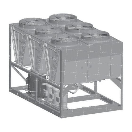
FORM QCC3-NM1 SECTION 2: PRODUCT DESCRIPTION ISSUE DATE: 12/19/2023 Unit components FAN ASSEMBLIES CONTROL PANEL COMPRESSORS CONDENSER COILS POWER PANEL FIGURE 2 - UNIT COMPONENTS FRONT Quantech... -
Page 21: Figure 3 - Power Panel Components
FORM QCC3-NM1 SECTION 2: PRODUCT DESCRIPTION ISSUE DATE: 12/19/2023 LD13248 Item Description Fan contactor Fan fuses Fan contactor Disconnect switch (optional) XTBF1 Compressor contactors Compressor overloads FIGURE 3 - POWER PANEL COMPONENTS Quantech... -
Page 22: Figure 4 - Power Panel / Control Components
FORM QCC3-NM1 SECTION 2: PRODUCT DESCRIPTION ISSUE DATE: 12/19/2023 LD13248b Item Description Fan contactor Fan fuses Control relay Microcomputer control center Display Keypad XTBC1 Microboard XTCB2 XTBF2 Compressor contactors Compressor overloads FIGURE 4 - POWER PANEL / CONTROL COMPONENTS Quantech... -
Page 23: Nomenclature (Pin)
FORM QCC3-NM1 SECTION 2: PRODUCT DESCRIPTION ISSUE DATE: 12/19/2023 Nomenclature 145C E = R-410A J = R-454B TABLE 1 - PRODUCT IDENTIFICATION NUMBER (PIN) FEATURE FEATURE DESCRIPTION OPTION OPTION DESCRIPTION MODEL Model (PIN 1-4) QCC3 QCC3 080C 080C 085C 085C 090C 090C 100C... - Page 24 FORM QCC3-NM1 SECTION 2: PRODUCT DESCRIPTION ISSUE DATE: 12/19/2023 TABLE 1: PRODUCT IDENTIFICATION NUMBER (PIN), CONT’D FEATURE FEATURE DESCRIPTION OPTION OPTION DESCRIPTION 200/3/60 230/3/60 380/3/60 VOLTS Voltage (PIN 11 and 12) 460/3/60 380-415/3/50 575/3/60 STARTER Starter (PIN 13) Across the Line starter Design Series A (MicroChannel) DESIGN Design Series (PIN 14)
- Page 25 FORM QCC3-NM1 SECTION 2: PRODUCT DESCRIPTION ISSUE DATE: 12/19/2023 TABLE 1: PRODUCT IDENTIFICATION NUMBER (PIN), CONT’D FEATURE FEATURE DESCRIPTION OPTION OPTION DESCRIPTION Standard Valves Req’d VALVES Valves (PIN 32) Special Optional Valves Req’d No Hot Gas Bypass required HGBP Hot Gas Bypass (PIN 33) Hot Gas Bypass required - 1 circuit Special Hot Gas Bypass required GAUGE...
- Page 26 FORM QCC3-NM1 SECTION 2: PRODUCT DESCRIPTION ISSUE DATE: 12/19/2023 TABLE 1: PRODUCT IDENTIFICATION NUMBER (PIN), CONT’D FEATURE FEATURE DESCRIPTION OPTION OPTION DESCRIPTION No Enclosure required Wire (Full Unit) Encl Panels (factory) Wire (Full Unit) Encl Panels (field) Wire/Louvered Encl Panels (factory) Wire/Louvered Encl Panels (field) Louvered (Cond only) Encl Panels (factory) ENCL...
-
Page 27: Refrigerant Flow Diagram
FORM QCC3-NM1 SECTION 2: PRODUCT DESCRIPTION ISSUE DATE: 12/19/2023 Refrigerant flow diagram LD04284A FIGURE 5 - REFRIGERANT FLOW DIAGRAM Quantech... -
Page 28: Process And Instrumentation Diagram
FORM QCC3-NM1 SECTION 2: PRODUCT DESCRIPTION ISSUE DATE: 12/19/2023 Process and instrumentation diagram Control Functions: DV - Displa y Value Fans Fans Components: CHT - Chilled Liquid Temperature HPC - High Pressure Cutout Pressure Relief Valve LPC - Low Pressure Cutout HPL - High Pressure Load Limiting Ser vice (Ball) Valve LTC - Low Temperature Cutout... -
Page 29: Section 3: Handling And Storage
FORM QCC3-NM1 ISSUE DATE: 12/19/2023 Section 3: Handling and storage Delivery and storage Unit rigging To ensure consistent quality and maximum reliability, Use spreader bars to avoid lifting chains hitting the all units are tested and inspected before leaving the fac- unit. - Page 30 FORM QCC3-NM1 SECTION 3: HANDLING AND STORAGE ISSUE DATE: 12/19/2023 Moving the condensing unit Lifting weights Prior to moving the unit, ensure that the installation For details of weights and weight distribution, refer to site is suitable for installing the unit and is easily ca- the data shipped in the unit information packet and unit pable of supporting the weight of the unit and all as- nameplate.
-
Page 31: Section 4: Installation
FORM QCC3-NM1 ISSUE DATE: 12/19/2023 Section 4: Installation To ensure warranty coverage, this equip- Location and clearances ment must be commissioned and serviced These units are designed for outdoor installations on by an authorized Quantech service ground level, rooftop, or beside a building. Due to the mechanic or a qualified service person properties of the refrigerant, never install the chiller in- experienced in equipment installation. -
Page 32: Spring Isolators: Optional
FORM QCC3-NM1 SECTION 4: INSTALLATION ISSUE DATE: 12/19/2023 Consult the building contractor or architect if the roof is Ductwork connection bonded. Roof installations should have wooden beams Recommendations of the Building Services Research (treated to reduce deterioration), cork, rubber, or vibra- Association. -
Page 33: Compressor Heaters
FORM QCC3-NM1 SECTION 4: INSTALLATION ISSUE DATE: 12/19/2023 Copper power wiring only should be used for supply- Electrical wiring ing power to the unit. This is recommended to avoid Field wiring safety and reliability issues resulting from connection failure at the power connections to the unit. Aluminum Power wiring must be provided through a fused dis- wiring is not recommended due to thermal character- connect switch to the unit terminals (or optional mold-... - Page 34 FORM QCC3-NM1 SECTION 4: INSTALLATION ISSUE DATE: 12/19/2023 See Air Proving Switch/Remote Start-Stop signal to the evaporator blower contactor. Contacts will Contacts. close whenever the daily schedule is programmed for cooling. See Figure 10 on page 41 and unit wiring diagram.
-
Page 35: Compressor Heaters
FORM QCC3-NM1 SECTION 4: INSTALLATION ISSUE DATE: 12/19/2023 Compressor heaters Refrigerant piping reference Compressor heaters are standard on all models. If pow- Copper line sizing er is OFF more than two hours, the crankcase heaters When selecting pipe diameter and material for remote must be energized for 18 h to 24 h prior to restarting a condenser piping systems, it is recommended that compressor. -
Page 36: Table 2 - Fitting Equivalent Lengths
FORM QCC3-NM1 SECTION 4: INSTALLATION ISSUE DATE: 12/19/2023 TABLE 2 - FITTING EQUIVALENT LENGTHS *COPPER FITTING EQUIVALENT LENGTHS LINE SIZE O.D. SHORT-RADIUS ELL LONG-RADIUS ELL 3/4 in. (19 mm) 6.5 ft. (2 m) 4.5 ft. (1.4 m) 7/8 in. (22 mm) 7.8 ft. -
Page 37: Table 5 - Refrigerant Line Connections
FORM QCC3-NM1 SECTION 4: INSTALLATION ISSUE DATE: 12/19/2023 TABLE 5 - REFRIGERANT LINE CONNECTIONS REFRIGERANT LINE SUCTION LINE LIQUID LINE CONNECTION MODEL SYSTEM VELOCITY TONS COPPER NOMINAL COPPER NUMBER NUMBER @ NOMINAL SUCTION LIQUID TYPE L TONS TYPE L CAPACITY INCHES OD UNLOADED INCHES OD... -
Page 38: Oil Traps
FORM QCC3-NM1 SECTION 4: INSTALLATION ISSUE DATE: 12/19/2023 Refrigerant line sizing Condenser below evaporator Refrigerant piping systems must be designed to pro- When the condensing unit is located below the evapo- vide practical line sizes without excessive pressure rator, the liquid line must be designed for both friction drops, prevent compressor oil from being “trapped”... -
Page 39: Refrigerant Piping Notes
FORM QCC3-NM1 SECTION 4: INSTALLATION ISSUE DATE: 12/19/2023 TABLE 6 - REFRIGERANT LINE PRESSURE DROPS (IMPERIAL) SUCTION LINE LIQUID LINE VELOCITY MODEL SYSTEM NOMINAL COPPER PRESSURE NOMINAL COPPER PRESSURE @ NOMINAL NUMBER NUMBER TONS TYPE L DROP TONS TYPE L DROP CAPACITY INCHES OD... -
Page 40: Figure 8 - Single-Point Supply Connection - Terminal Block, Non-Fused Disconnect Switch Or Circuit Breaker
FORM QCC3-NM1 SECTION 4: INSTALLATION ISSUE DATE: 12/19/2023 Power Panel Power Panel Power Panel Control Panel Control Panel Control Panel Terminal Block, Terminal Block, MICROPANEL MICROPANEL NF Disconnect SW NF Disconnect SW or Circuit Breaker or Circuit Breaker CTB2 CTB2 CTB2 Flow Switch Flow Switch... -
Page 41: Control Wiring
FORM QCC3-NM1 SECTION 4: INSTALLATION ISSUE DATE: 12/19/2023 Control wiring PWM INPUT (CAN ONLY BE USED WITH DISCHARGE AIR TEMP CONTROL) LOAD LIMIT INPUT AIR PROVING SWITCH (DISCHARGE AIR TEMP CONTROL AND SUCTION PRESSURE CONTROL) AND REMOTE START/STOP SYSTEM 1 THERMOSTAT (SUCTION PRESSURE CONTROL ONLY) (JUMPER FOR DISCHARGE AIR TEMP CONTROL) SYSTEM 2 THERMOSTAT (SUCTION PRESSURE CONTROL ONLY) XTBC1... - Page 42 FORM QCC3-NM1 SECTION 4: INSTALLATION ISSUE DATE: 12/19/2023 THIS PAGE INTENTIONALLY LEFT BLANK. Quantech...
-
Page 43: Section 5: Technical Data
FORM QCC3-NM1 ISSUE DATE: 12/19/2023 Section 5: Technical data Operational limitations Voltage limitations The following voltage limitations are absolute and Temperature and flows operation beyond these limitations may cause serious Excessive flow will cause damage to the damage to the compressor. cooler. -
Page 44: Physical Data
FORM QCC3-NM1 SECTION 5: TECHNICAL DATA ISSUE DATE: 12/19/2023 Physical data QCC3080C_ – QCC3160C_ 60 Hz TABLE 8 - PHySICAL DATA (IMPERIAL) REFRIGERANT R-410A AND MODEL NUMBER - STANDARD EFFICIENCY UNITS R-454B GENERAL UNIT DATA 080CZE 085CZE 090CZE 100CYE 110CYE 130CZE 145CZE 160CZE... -
Page 45: Electrical Data
FORM QCC3-NM1 SECTION 5: TECHNICAL DATA ISSUE DATE: 12/19/2023 Electrical data TABLE 9 - MICRO PANEL POWER SUPPLy OVER CURRENT PROTECTION, CONTROL UNIT VOLTAGE POWER SEE NOTE B NF DISC SW UNIT NOTE A MODELS W/O VOLTAGE MINIMUM MAXIMUM CONTROL 115-1-60/50 TRANS 30 A / 240V... -
Page 46: Table 11 - Standard Efficiency Unit Electrical Data (4 Compr) R-410A, Single Point
FORM QCC3-NM1 SECTION 5: TECHNICAL DATA ISSUE DATE: 12/19/2023 Single point TABLE 11 - STANDARD EFFICIENCy UNIT ELECTRICAL DATA (4 COMPR) R-410A, SINGLE POINT SYSTEM # 1 DUAL COMPR 1 COMPR 2 PUMP VOLT PUMP DUAL ELEM MODEL EFF. MODEL CODE ELEM FUSE... - Page 47 FORM QCC3-NM1 SECTION 5: TECHNICAL DATA ISSUE DATE: 12/19/2023 TABLE 11 - STANDARD EFFICIENCy UNIT ELECTRICAL DATA (4 COMPR) R-410A, SINGLE POINT, CONT’D SYSTEM # 1 SYSTEM # 2 COMPR 3 COMPR 1 COMPR 2 COMPR 3 44.0 44.0 37.0 37.0 23.1 23.1...
-
Page 48: Table 13 - Standard Efficiency Unit Electrical Data (6 Compr) R-410A, Single Point
FORM QCC3-NM1 SECTION 5: TECHNICAL DATA ISSUE DATE: 12/19/2023 TABLE 13 - STANDARD EFFICIENCy UNIT ELECTRICAL DATA (6 COMPR) R-410A, SINGLE POINT SYSTEM # 1 DUAL COMPR 1 COMPR 2 Pump Volt Pump DUAL ELEM MODEL Eff. Model Code N/F DS ELEM FUSE FUSE... - Page 49 FORM QCC3-NM1 SECTION 5: TECHNICAL DATA ISSUE DATE: 12/19/2023 TABLE 13 - STANDARD EFFICIENCy UNIT ELECTRICAL DATA (6 COMPR) R-410A, SINGLE POINT, CONT’D SYSTEM # 1 SYSTEM # 2 COMPR 3 COMPR 1 COMPR 2 COMPR 3 44.0 44.0 37.0 37.0 23.1 23.1...
-
Page 50: Table 16 - Standard Efficiency Unit Electrical Data (4 Compr) R-454B, Single Point
FORM QCC3-NM1 SECTION 5: TECHNICAL DATA ISSUE DATE: 12/19/2023 TABLE 16 - STANDARD EFFICIENCy UNIT ELECTRICAL DATA (4 COMPR) R-454B, SINGLE POINT SYSTEM # 1 DUAL COMPR 1 COMPR 2 PUMP VOLT PUMP DUAL ELEM MODEL EFF. MOD- CODE ELEM FUSE FUSE 106.2... - Page 51 FORM QCC3-NM1 SECTION 5: TECHNICAL DATA ISSUE DATE: 12/19/2023 TABLE 16 - STANDARD EFFICIENCy UNIT ELECTRICAL DATA (4 COMPR) R-454B, SINGLE POINT, CONT’D SYSTEM # 1 SYSTEM # 2 COMPR 3 COMPR 1 COMPR 2 COMPR 3 44.0 106.2 106.2 44.0 37.0 106.2...
-
Page 52: Table 19 - High Efficiency Unit Electrical Data (5 Compr) R-454B, Single Point
FORM QCC3-NM1 SECTION 5: TECHNICAL DATA ISSUE DATE: 12/19/2023 TABLE 18 - STANDARD EFFICIENCy UNIT ELECTRICAL DATA (6 COMPR) R-454B, , SINGLE POINT CONT’D SYSTEM # 1 DUAL COMPR 1 COMPR 2 Pump Volt Pump DUAL ELEM MODEL Eff. Model Code N/F DS ELEM... - Page 53 FORM QCC3-NM1 SECTION 5: TECHNICAL DATA ISSUE DATE: 12/19/2023 TABLE 18 - STANDARD EFFICIENCy UNIT ELECTRICAL DATA (6 COMPR) R-454B, SINGLE POINT, CONT’D SYSTEM # 1 SYSTEM # 2 COMPR 3 COMPR 1 COMPR 2 COMPR 3 57.7 44.0 57.7 57.7 57.7 44.0...
-
Page 54: Table 21 - Standard Efficiency Unit Electrical Data (4 Compr) R-410A, Dual Point
FORM QCC3-NM1 SECTION 5: TECHNICAL DATA ISSUE DATE: 12/19/2023 Dual point TABLE 21 - STANDARD EFFICIENCy UNIT ELECTRICAL DATA (4 COMPR) R-410A, DUAL POINT System 1 System 2 VOLT DUAL DUAL DUAL DUAL MODEL EFF MIN N/ MIN N/F Code ELEM ELEM ELEM... - Page 55 FORM QCC3-NM1 SECTION 5: TECHNICAL DATA ISSUE DATE: 12/19/2023 TABLE 21 - STANDARD EFFICIENCy UNIT ELECTRICAL DATA (4 COMPR) R-410A, DUAL POINT, CONT’D SYSTEM # 1 SYSTEM # 2 COMPR 1 COMPR 2 COMPR 3 COND FANS COMPR 1 COMPR 2 COMPR 3 COND FANS RLA LRA RLA LRA RLA LRA QTY...
-
Page 56: Table 23 - Standard Efficiency Unit Electrical Data (6 Compr) R-410A, Dual Point
FORM QCC3-NM1 SECTION 5: TECHNICAL DATA ISSUE DATE: 12/19/2023 TABLE 23 - STANDARD EFFICIENCy UNIT ELECTRICAL DATA (6 COMPR) R-410A, DUAL POINT System 1 System 2 VOLT DUAL DUAL DUAL DUAL MODEL EFF MIN N/ MIN N/F Code ELEM ELEM ELEM ELEM FUSE and... - Page 57 FORM QCC3-NM1 SECTION 5: TECHNICAL DATA ISSUE DATE: 12/19/2023 TABLE 23 - STANDARD EFFICIENCy UNIT ELECTRICAL DATA (6 COMPR) R-410A, DUAL POINT, CONT’D SYSTEM # 1 SYSTEM # 2 COMPR 1 COMPR 2 COMPR 3 COND FANS COMPR 1 COMPR 2 COMPR 3 COND FANS RLA LRA RLA LRA RLA LRA QTY...
-
Page 58: Table 26 - Standard Efficiency Unit Electrical Data (4 Compr) R-454B, Dual Point
FORM QCC3-NM1 SECTION 5: TECHNICAL DATA ISSUE DATE: 12/19/2023 TABLE 26 - STANDARD EFFICIENCy UNIT ELECTRICAL DATA (4 COMPR) R-454B, DUAL POINT System 1 System 2 VOLT DUAL DUAL DUAL DUAL MODEL EFF MIN N/ MIN N/F Code ELEM ELEM ELEM ELEM FUSE and... - Page 59 FORM QCC3-NM1 SECTION 5: TECHNICAL DATA ISSUE DATE: 12/19/2023 TABLE 26 - STANDARD EFFICIENCy UNIT ELECTRICAL DATA (4 COMPR) R-454B, DUAL POINT, CONT’D SYSTEM # 1 SYSTEM # 2 COMPR 1 COMPR 2 COMPR 3 COND FANS COMPR 1 COMPR 2 COMPR 3 COND FANS LRA QTY...
-
Page 60: Table 29 - High Efficiency Unit Electrical Data (5 Compr) R-454B, Dual Point
FORM QCC3-NM1 SECTION 5: TECHNICAL DATA ISSUE DATE: 12/19/2023 TABLE 28 - STANDARD EFFICIENCy UNIT ELECTRICAL DATA (6 COMPR) R-454B, , DUAL POINT, CONT’D System 1 System 2 VOLT DUAL DUAL DUAL DUAL MODEL EFF MIN N/ MIN N/F Code ELEM ELEM ELEM... - Page 61 FORM QCC3-NM1 SECTION 5: TECHNICAL DATA ISSUE DATE: 12/19/2023 TABLE 28 - STANDARD EFFICIENCy UNIT ELECTRICAL DATA (6 COMPR) R-454B, DUAL POINT, CONT’D SYSTEM # 1 SYSTEM # 2 COMPR 1 COMPR 2 COMPR 3 COND FANS COMPR 1 COMPR 2 COMPR 3 COND FANS LRA QTY...
-
Page 62: Table 31 - Lug Sizing
FORM QCC3-NM1 SECTION 5: TECHNICAL DATA ISSUE DATE: 12/19/2023 TABLE 31 - LUG SIZING NON-FUSE DISC SW. CIRCUIT BREAKER TERMINAL BLOCK MODEL RATING SIZE RATING SIZE S6-600 S6: (2) 250kcmil - 500kcmil S5-400 S5: (2) 3/0 - 250kcmil (4) 4AWG - 500kcmil S6-600 S6: (2) 250kcmil - 500kcmil S5-400... - Page 63 FORM QCC3-NM1 SECTION 5: TECHNICAL DATA ISSUE DATE: 12/19/2023 of the rated load amps for all other loads includ- Electrical notes ed in the circuit. Otherwise, HACR-type circuit 1. Minimum Circuit Ampacity (MCA) is based on breakers must be used. Maximum HACR circuit 125% of the rated load amps for the largest mo- breaker rating is based on 225% of the rated load tor plus 100% of the rated load amps for all other...
- Page 64 FORM QCC3-NM1 SECTION 5: TECHNICAL DATA ISSUE DATE: 12/19/2023 Electrical notes and legend DESIGNATION DESCRIPTION DESIGNATION DESCRIPTION Accessory - MP Motor Pump - ADIS Display Board Not Used - AMB Micro Board Protective Earth - BAMB Ambient Pulse Width Modulation Temp Reset Or Remote Unload 2Nd Step - BDAT Discharge Air Temperature...
- Page 65 FORM QCC3-NM1 SECTION 5: TECHNICAL DATA ISSUE DATE: 12/19/2023 Electrical notes and legend (Continued) GENERAL This drawing is based on IEC symbols. Field wiring to be in accordance with the relevant electrical code as well as all other applicable codes and specifications.
- Page 66 FORM QCC3-NM1 SECTION 5: TECHNICAL DATA ISSUE DATE: 12/19/2023 Electrical notes and legend (continued) GENERAL For optional hydro kit. Heater -EPH is fitted and wired as shown. On single pump -KP1, -QMMSP1 and -MP1 are fitted and wired as shown. On two pump hydro kits -KP2, -QMMSP2 and -MP2 are also fitted and wired as shown. Current measurement option wired as show.
- Page 67 FORM QCC3-NM1 SECTION 5: TECHNICAL DATA ISSUE DATE: 12/19/2023 THIS PAGE INTENTIONALLy LEFT BLANK. Quantech...
-
Page 68: Wiring Diagrams
FORM QCC3-NM1 SECTION 5: TECHNICAL DATA ISSUE DATE: 12/19/2023 Wiring Diagrams 035-21583-101 REV D FIGURE 11 - ELEMENTARy WIRING DIAGRAM Quantech... - Page 69 FORM QCC3-NM1 SECTION 5: TECHNICAL DATA ISSUE DATE: 12/19/2023 FIGURE 11 - ELEMENTARy WIRING DIAGRAM (CONT’D) Quantech...
- Page 70 FORM QCC3-NM1 SECTION 5: TECHNICAL DATA ISSUE DATE: 12/19/2023 035-21583-102 REVD FIGURE 11 - ELEMENTARy WIRING DIAGRAM (CONT’D) Quantech...
- Page 71 FORM QCC3-NM1 SECTION 5: TECHNICAL DATA ISSUE DATE: 12/19/2023 FIGURE 11 - ELEMENTARy WIRING DIAGRAM (CONT’D) Quantech...
- Page 72 FORM QCC3-NM1 SECTION 5: TECHNICAL DATA ISSUE DATE: 12/19/2023 FIGURE 11 - ELEMENTARy WIRING DIAGRAM (CONT’D) Quantech...
- Page 73 FORM QCC3-NM1 SECTION 5: TECHNICAL DATA ISSUE DATE: 12/19/2023 FIGURE 11 - ELEMENTARy WIRING DIAGRAM (CONT’D) Quantech...
- Page 74 FORM QCC3-NM1 SECTION 5: TECHNICAL DATA ISSUE DATE: 12/19/2023 035-21589-107 REV A FIGURE 11 - ELEMENTARy WIRING DIAGRAM (CONT’D) Quantech...
- Page 75 FORM QCC3-NM1 SECTION 5: TECHNICAL DATA ISSUE DATE: 12/19/2023 FIGURE 11 - ELEMENTARy WIRING DIAGRAM (CONT’D) Quantech...
- Page 76 FORM QCC3-NM1 SECTION 5: TECHNICAL DATA ISSUE DATE: 12/19/2023 035-21589-106 REVE FIGURE 11 - ELEMENTARy WIRING DIAGRAM (CONT’D) Quantech...
- Page 77 FORM QCC3-NM1 SECTION 5: TECHNICAL DATA ISSUE DATE: 12/19/2023 FIGURE 11 - ELEMENTARy WIRING DIAGRAM (CONT’D) Quantech...
-
Page 78: Power Options Connection Diagram
FORM QCC3-NM1 SECTION 5: TECHNICAL DATA ISSUE DATE: 12/19/2023 Power options connection diagram 035-21589-103 REVB LD13234A FIGURE 12 - POWER OPTIONS CONNECTION DIAGRAM Quantech... - Page 79 FORM QCC3-NM1 SECTION 5: TECHNICAL DATA ISSUE DATE: 12/19/2023 LD13901 FIGURE 12 - POWER OPTIONS CONNECTION DIAGRAM (CONT’D) Quantech...
- Page 80 FORM QCC3-NM1 SECTION 5: TECHNICAL DATA ISSUE DATE: 12/19/2023 035-21589-101 REVC FIGURE 12 - POWER OPTIONS CONNECTION DIAGRAM (CONT’D) Quantech...
- Page 81 FORM QCC3-NM1 SECTION 5: TECHNICAL DATA ISSUE DATE: 12/19/2023 FIGURE 12 - POWER OPTIONS CONNECTION DIAGRAM (CONT’D) Quantech...
-
Page 82: Figure 13 - Single Point And Dual Point Wiring
FORM QCC3-NM1 SECTION 5: TECHNICAL DATA ISSUE DATE: 12/19/2023 035-21583-116_rev - FIGURE 13 - SINGLE POINT AND DUAL POINT WIRING Quantech... - Page 83 FORM QCC3-NM1 SECTION 5: TECHNICAL DATA ISSUE DATE: 12/19/2023 THIS PAGE INTENTIONALLy LEFT BLANK. Quantech...
-
Page 84: Wiring
FORM QCC3-NM1 SECTION 5: TECHNICAL DATA ISSUE DATE: 12/19/2023 Wiring 035-21583-106 REVA LD13238 FIGURE 14 - WIRING Quantech... - Page 85 FORM QCC3-NM1 SECTION 5: TECHNICAL DATA ISSUE DATE: 12/19/2023 LD13239 FIGURE 14 - WIRING (CONT’D) Quantech...
-
Page 86: Micro Panel Connections
FORM QCC3-NM1 SECTION 5: TECHNICAL DATA ISSUE DATE: 12/19/2023 Micro panel connections 035-21589-102 REVD FIGURE 15 - MICRO PANEL CONNECTIONS Quantech... - Page 87 FORM QCC3-NM1 SECTION 5: TECHNICAL DATA ISSUE DATE: 12/19/2023 FIGURE 15 - MICRO PANEL CONNECTIONS (CONT’D) Quantech...
-
Page 88: Figure 16 - Elementary Diagram
FORM QCC3-NM1 SECTION 5: TECHNICAL DATA ISSUE DATE: 12/19/2023 035-21583-103 REV. B LD13992A FIGURE 16 - ELEMENTARy DIAGRAM Quantech... - Page 89 FORM QCC3-NM1 SECTION 5: TECHNICAL DATA ISSUE DATE: 12/19/2023 LD13993A FIGURE 16 - ELEMENTARy DIAGRAM (CONT’D) Quantech...
- Page 90 FORM QCC3-NM1 SECTION 5: TECHNICAL DATA ISSUE DATE: 12/19/2023 035-21589-105 REVA FIGURE 16 - ELEMENTARy DIAGRAM (CONT’D) Quantech...
- Page 91 FORM QCC3-NM1 SECTION 5: TECHNICAL DATA ISSUE DATE: 12/19/2023 FIGURE 16 - ELEMENTARy DIAGRAM (CONT’D) Quantech...
-
Page 92: Dimensions
FORM QCC3-NM1 SECTION 5: TECHNICAL DATA ISSUE DATE: 12/19/2023 Dimensions Dimensions – QCC3080C TO 090C (Imperial) CONNECTION SYSTEM 1 SYSTEM 2 LENGTH WIDTH HEIGHT SIZES DIMENSIONS DIMENSIONS MODEL SUCTION LIQUID SUCTION LIQUID SUCTION LIQUID IN 1/2 OUT 1/2 QCC3080CZE 116.1 88.3 95.3 89.7 43.9... - Page 93 FORM QCC3-NM1 SECTION 5: TECHNICAL DATA ISSUE DATE: 12/19/2023 Dimensions – QCC3100C TO 130C 5/8 in. dia. mounting holes (typ) Top view L1-OUT S1-IN S2-IN L2-OUT Front view Side view LD19671a CONNECTION SYSTEM 1 SYSTEM 2 LENGTH WIDTH HEIGHT SIZES DIMENSIONS DIMENSIONS MODEL...
- Page 94 FORM QCC3-NM1 SECTION 5: TECHNICAL DATA ISSUE DATE: 12/19/2023 Dimensions – QCC3145C TO 160C CONNECTION SYSTEM 1 SYSTEM 2 LENGTH WIDTH HEIGHT SIZES DIMENSIONS DIMENSIONS MODEL SUCTION LIQUID SUCTION LIQUID SUCTION LIQUID IN 1/2 OUT 1/2 QCC3145CZE 187.5 88.3 95.3 89.7 43.9 3.1/2.7 1.4/1.1...
-
Page 95: Clearances
FORM QCC3-NM1 SECTION 5: TECHNICAL DATA ISSUE DATE: 12/19/2023 Clearances (2 m) (1.3 m) LD13243 NOTES: 1. No obstructions allowed above the unit. 2. Only one adjacent wall may be higher than the unit. 3. Adjacent units should be 10 ft (3 m) apart. FIGURE 17 - UNIT CLEARANCES –... -
Page 96: Weight Distribution And Isolator Mounting Positions
FORM QCC3-NM1 SECTION 5: TECHNICAL DATA ISSUE DATE: 12/19/2023 Weight distribution and isolator and on the following page. The drawing will show the isolator locations along with the weight in pounds and mounting positions kilograms at the specific location, isolator position, General and location measurements for each isolator. -
Page 97: Isolator Information
FORM QCC3-NM1 SECTION 5: TECHNICAL DATA ISSUE DATE: 12/19/2023 Isolator information 1 in. deflection spring isolator cross-reference 5/8" Ø1/2" H" C" T" B" L" D" W" LD13759A MOUNT DIMENSION DATA (INCHES) TYPE 7-3/4 6-1/2 4-3/4 5-5/8 10-1/2 9-1/4 7-3/4 9/16 RATED CAPACITY (FOR UNITS WITH ALL LOAD POINTS LESS THAN 1785 LB (810 KG) MODEL NUMBER... - Page 98 FORM QCC3-NM1 SECTION 5: TECHNICAL DATA ISSUE DATE: 12/19/2023 5. Place equipment on top of isolators making sure 1 in. deflection spring isolators installation that mounting holes of the equipment line up with instructions isolator positioning pin (“h”). 1. Read instructions in their entirety before begin- ning installation.
- Page 99 FORM QCC3-NM1 SECTION 5: TECHNICAL DATA ISSUE DATE: 12/19/2023 2 in. deflection seismic isolator cross-reference Y2RS 1-1/8" 5" 5/8" 2-3/4" 2-3/4" 12" 3/8" GAP 5/8-11UNC Ø3/4" TYP. (4) TYP.(4) 3/4" 7/8" 1/2" LIMIT STOP and 8-3/8" OPER. HEIGHT 12-1/4" 14" 3-1/2"...
- Page 100 FORM QCC3-NM1 SECTION 5: TECHNICAL DATA ISSUE DATE: 12/19/2023 Seismic isolator installation and adjustment 1. Read instructions in their entirety before begin- with a minimum 3/8 fillet welds 2 in. long at 3 in. ning installation. o.C. For a minimum total weld of 10 in. (All sides of equipment or bracket resting on top plate ("a") 2.
- Page 101 FORM QCC3-NM1 SECTION 5: TECHNICAL DATA ISSUE DATE: 12/19/2023 Durulene isolator cross-reference RD-style isolators MOLDED DURULENE ø D THRU TYP 2 PLACES Notes: 1. All dimensions are inches, interpreted per ANSI y14. 2. See the following page for installation instructions. 3.
- Page 102 FORM QCC3-NM1 SECTION 5: TECHNICAL DATA ISSUE DATE: 12/19/2023 4. Bolt or anchor all isolators to supporting structure Installation of durulene vibration isolators utilizing base Thru holes ("b"). 1. Read instructions in their entirety before begin- ning installation. 5. Remove top bolt and top washer. Place equip- ment on top of isolators so That mounting holes 2.
-
Page 103: Section 6: Commissioning
FORM QCC3-NM1 ISSUE DATE: 12/19/2023 Section 6: Commissioning Commissioning Service and oil line valves Commissioning of this unit should only Open each compressor suction and discharge service be carried out by Quantech Authorized valve. If valves are of the back-seat type, open them personnel. -
Page 104: Preparation: Power On
FORM QCC3-NM1 SECTION 6: COMMISSIONING ISSUE DATE: 12/19/2023 Grounding Switch settings Verify that the unit’s protective ground terminal(s) are Ensure that the condensing unit OFF/ON UNIT switch properly connected to a suitable grounding point. En- at the bottom of the keypad is OFF. Place the optional sure that all unit internal ground connections are tight. - Page 105 FORM QCC3-NM1 SECTION 6: COMMISSIONING ISSUE DATE: 12/19/2023 QCC3 Installation and Startup Checklist Supersedes: QCC3-CL2 (417) Form: QCC3-CL2 (1123) Customer: ______________________________________ Job name: ______________________________________ Address: _______________________________________ Location: _______________________________________ Phone: _________________________________________ Customer order number: __________________________ Phone number: Order number: Contract number: ___________________________ ___________________________ _______________________________...
- Page 106 FORM QCC3-NM1 SECTION 6: COMMISSIONING ISSUE DATE: 12/19/2023 Form QCC3-CL2 Issue date: 11/10/2023 C. Panel checks Table 1: Program values Power on, both unit switches off Options Value You are about to turn power on for this Display language machine. Safety is the main priority. SYS 1 switch Only qualified individuals are permit- ted to service this product.
- Page 107 FORM QCC3-NM1 SECTION 6: COMMISSIONING ISSUE DATE: 12/19/2023 Form QCC3-CL2 Issue date: 11/10/2023 4. Put the unit into service mode and cycle each con- D. CHECKING SUPERHEAT AND SUBCOOLING denser fan to ensure correct rotation. Refer to Form The subcooling temperature of each system can be calcu- QCC3-NM1, Service and Troubleshooting section lated by recording the temperature of the liquid line at the for more information.
- Page 108 FORM QCC3-NM1 SECTION 6: COMMISSIONING ISSUE DATE: 12/19/2023 Form QCC3-CL2 Issue date: 11/10/2023 Record the suction temperature, suction pressure, suc- tion saturation temperature, and superheat of each system below: SYS 1 SYS 2 Suction temp. = _______ _______ °F Suction Pressure = _______ _______ psig Saturation temp.
-
Page 109: Section 7: Unit Controls
FORM QCC3-NM1 ISSUE DATE: 12/19/2023 Section 7: Unit controls LD19046 Introduction Microprocessor board The Quantech MicroComputer Control Center is a mi- The Microprocessor Board is the controller and deci- croprocessor based control system designed to provide sion maker in the control panel. System inputs such the entire control for the condensing unit. -
Page 110: Unit Switch
FORM QCC3-NM1 SECTION 7: UNIT CONTROLS ISSUE DATE: 12/19/2023 Unit switch Battery back-up A unit ON/OFF switch is just underneath the keypad. The Microprocessor Board contains a Real Time Clock This switch allows the operator to turn the entire unit integrated circuit chip with an internal battery backup. -
Page 111: Status Key
FORM QCC3-NM1 SECTION 7: UNIT CONTROLS ISSUE DATE: 12/19/2023 Status key 00066VIP Unit status F L O W S W I T C H / R E M S T O P Pressing the STATUS key will enable the operator to R U N P E R M determine current unit operating status. - Page 112 FORM QCC3-NM1 SECTION 7: UNIT CONTROLS ISSUE DATE: 12/19/2023 When this message appears, suction pressure limiting S Y S T I M E R is in effect. The suction pressure limit is a control point S Y S T I M E R that limits the loading of a system when the suction pressure drops to within 15% above the suction pres- The anti-recycle timer message shows the amount of...
- Page 113 FORM QCC3-NM1 SECTION 7: UNIT CONTROLS ISSUE DATE: 12/19/2023 At system start, the cutout is set to 10% of programmed Fault safety status messages value. During the next 3 minutes the cutout point is Safety Status messages appear when safety thresholds ramped up to the programmed cutout point.
- Page 114 FORM QCC3-NM1 SECTION 7: UNIT CONTROLS ISSUE DATE: 12/19/2023 When the sensor senses a high temperature, it opens System Discharge Superheat drops below 18°F and the motor protector circuit in the compressor causing trips after 5 minutes have passed. The fault resets if the the compressor to shut down.
- Page 115 FORM QCC3-NM1 SECTION 7: UNIT CONTROLS ISSUE DATE: 12/19/2023 If a low battery is detected, it should be replaced as U N I T F A U L T : soon as possible. The programmed values will all be 1 1 5 V A C U N D E R V O L T A G E lost and the unit will be prevented from running on the...
-
Page 116: Figure 19 - Status Key Messages Quick Reference List
FORM QCC3-NM1 SECTION 7: UNIT CONTROLS ISSUE DATE: 12/19/2023 Status key messages STATUS KEY MESSAGES General Messages Fault Messages System Safeties Unit Safeties Unit Warnings Unit Switch Off Shutdown Remote Controlled System X High Disch Pressure Low Ambient Temp Low Battery Shutdown Daily Schedule System X Low Suct Pressure... -
Page 117: Display/Print Keys
FORM QCC3-NM1 SECTION 7: UNIT CONTROLS ISSUE DATE: 12/19/2023 Display/print keys 00067VIP The Display/Print keys allow the user to retrieve sys- able under the Oper Data key in the order that they are tem and unit information that is useful for monitoring displayed. - Page 118 FORM QCC3-NM1 SECTION 7: UNIT CONTROLS ISSUE DATE: 12/19/2023 S Y S 7 2 . 1 P S I G L O A D T I M E R S E C = 2 2 7 . 0 P S I G U N L O A D T I M E R S E C...
- Page 119 FORM QCC3-NM1 SECTION 7: UNIT CONTROLS ISSUE DATE: 12/19/2023 A C T I V E R E M O T E C T R L S Y S A M P S 3 6 . 0 N O N E V O L T S 0 .
-
Page 120: Figure 20 - Operation Data
FORM QCC3-NM1 SECTION 7: UNIT CONTROLS ISSUE DATE: 12/19/2023 Oper data quick reference list Print key The following table is a quick reference list for infor- The PRINT key allows the operator to obtain a printout mation available under the OPER DATA key. of real-time system operating data or a history print- out of system data at the “instant of the fault”... - Page 121 FORM QCC3-NM1 SECTION 7: UNIT CONTROLS ISSUE DATE: 12/19/2023 History printout Pressing the PRINT key and then the HISTORY key SYSTEM 1 DATA COMP STATUS 1=OFF 2=OFF 3=OFF allows the operator to obtain a printout of informa- RUN TIME 0- 0- 0- 0 D-H-M-S tion relating to the last 6 Safety Shutdowns which oc- SUCTION PRESSURE 66 psig...
- Page 122 FORM QCC3-NM1 SECTION 7: UNIT CONTROLS ISSUE DATE: 12/19/2023 History displays L O C A L / R E M O T E M O D E The HISTORY key gives the user access to many unit X X X X X X X X X and system operating parameters at the time of a unit or system safety shutdown.
- Page 123 FORM QCC3-NM1 SECTION 7: UNIT CONTROLS ISSUE DATE: 12/19/2023 S Y S X X X X P S I G S U C T I O N P R E S S U R E R A N G E + / - X X X P S I G C U T O U T...
- Page 124 FORM QCC3-NM1 SECTION 7: UNIT CONTROLS ISSUE DATE: 12/19/2023 Displays for System 1 starting with SYS X NUMBER S Y S X X X X P S I G OF COMPS RUNNING X through SYS X AMPS = X X X X P S I G XXX.X VOLTS = X.X will be displayed first, fol- lowed by displays for System 2.
-
Page 125: Entry Keys
FORM QCC3-NM1 SECTION 7: UNIT CONTROLS ISSUE DATE: 12/19/2023 Entry keys 00068VIP The Entry Keys allows the user to view, change pro- Enter/adv key grammed values. The ENTRY keys consist of an ↑ The ENTER/ADV key must be pushed after any change (UP) arrow key, ↓... -
Page 126: Setpoints Keys
FORM QCC3-NM1 SECTION 7: UNIT CONTROLS ISSUE DATE: 12/19/2023 Setpoints keys 00069VIP Programming of the cooling setpoints, daily schedule, Following are the four possible messages that can be and safeties is accomplished by using the keys located displayed after pressing the COOLING SETPOINT under the SETPOINTS section. - Page 127 FORM QCC3-NM1 SECTION 7: UNIT CONTROLS ISSUE DATE: 12/19/2023 such as an BAS control. The message also indicates in Suction Pressure Control are the suction pressures that the control point is based on Discharge Air Tem- of each individual system on the condensing Unit and perature leaving the evaporator.
- Page 128 FORM QCC3-NM1 SECTION 7: UNIT CONTROLS ISSUE DATE: 12/19/2023 As with the other setpoints, the Up Arrow and Down After SUN (Sunday) schedule appears on the display Arrow keys are used to change the Temp Reset value. a subsequent press of the SCHEDULE/ADVANCE After using the UP and DOWN ARROWS to adjust DAY key will display the Holiday schedule.
- Page 129 FORM QCC3-NM1 SECTION 7: UNIT CONTROLS ISSUE DATE: 12/19/2023 chanical high pressure switch located in the refrigerant has timed out. If the lead system has run for less than 5 circuit. The system can restart when the discharge pres- minutes, 3 times in a row, the anti-recycle timer will be sure drops 40 psig (2.76 barg) below the cutout point.
- Page 130 FORM QCC3-NM1 SECTION 7: UNIT CONTROLS ISSUE DATE: 12/19/2023 A single system condensing unit MUST 460 VAC system trip volts have a jumper between terminals 13 - 17 For individual system high current trip programming on terminal block XTBC1. If the jumper on 460 VAC units: is not installed, which is the correct con- figuration for QCC3080 and 0160 units,...
-
Page 131: Table 32 - Cooling Setpoints Programmable Limits And Defaults
FORM QCC3-NM1 SECTION 7: UNIT CONTROLS ISSUE DATE: 12/19/2023 TABLE 32 - COOLING SETPOINTS PROGRAMMABLE LIMITS AND DEFAULTS SETPOINT VALUE LOW LIMIT HIGH LIMIT DEFAULT 45.0 °F 70.0°F 44.0°F Discharge Air Temp. Setpoint 7.2°C 21.1°C 12.7°C 3.0°F 10.0°F 5.0°F Discharge Air Temp. Range 1.7°C 5.6°C 2.8°C... -
Page 132: Figure 21 - Setpoints Quick Reference List
FORM QCC3-NM1 SECTION 7: UNIT CONTROLS ISSUE DATE: 12/19/2023 Oper data quick reference list This table provides a quick reference of the setpoints list for the Setpoints Keys. SETPOINTS KEYS Cooling Setpoints Key Schedule/ Program Mode (press key to adv.) Advance Day Key (press enter to adv.) Local/Remote Discharge... -
Page 133: Unit Keys
FORM QCC3-NM1 SECTION 7: UNIT CONTROLS ISSUE DATE: 12/19/2023 Unit keys OPTIONS OPTIONS CLOCK CLOCK 00070VIP Options key S Y S S W I T C H O F F There are many user programmable options under the S Y S S W I T C H OPTIONS key. - Page 134 FORM QCC3-NM1 SECTION 7: UNIT CONTROLS ISSUE DATE: 12/19/2023 The software may skip the low ambient selection, but a low ambient kit is still needed to operate below 25°F. D I S P L A Y U N I T S This mode displays system operating values in Scien- tific International Units of °C or barg.
- Page 135 FORM QCC3-NM1 SECTION 7: UNIT CONTROLS ISSUE DATE: 12/19/2023 The software may skip the Fan Control Option 11: Power fail restart message on QCC3 units. P O W E R F A I L R E S T A R T A U T O M A T I C Unit auto restarts after a power failure.
- Page 136 FORM QCC3-NM1 SECTION 7: UNIT CONTROLS ISSUE DATE: 12/19/2023 Press the ENTER key and the following message will Option 14: Refrigerant type be displayed until the update has been completed. The R E F R I G E R A N T T Y P E keypad and display will not respond during the update.
- Page 137 FORM QCC3-NM1 SECTION 7: UNIT CONTROLS ISSUE DATE: 12/19/2023 Option 18: Hot gas bypass type Clock The Hot Gas Bypass Type must be programmed based The CLOCK display shows the current day, time, and on the option installed. Some chillers will not have hot date.
-
Page 138: Figure 22 - Unit Keys Programming Quick Reference List
FORM QCC3-NM1 SECTION 7: UNIT CONTROLS ISSUE DATE: 12/19/2023 Options Key Expansion Valve Type (Press Options Key (Thermoplastic or Electric) to Adv.) (Programmed Under Service Display Language Mode, Viewable Only) Must be Programmed for Thermostatic System Switches On/Off Hot Gas Bypass Type Ambient Control (Standard or Low) Flashcard Data Logging... -
Page 139: Section 8: Unit Operation
FORM QCC3-NM1 ISSUE DATE: 12/19/2023 Section 8: Unit operation Capacity control Discharge pressure limit controls To initiate the start sequence of the unit, all run permis- The discharge pressure limit controls unload a sys- sive inputs must be satisfied (air proving/remote start/ tem before it reaches a safety limit due to high load stop switch), and no unit or system faults exist. -
Page 140: Figure 23 - Discharge Air Temperature Control
FORM QCC3-NM1 SECTION 8: UNIT OPERATION ISSUE DATE: 12/19/2023 20 sec. 30 sec. 60 sec. control range 60 sec. unloading unloading unloading (no compressor staging) loading 51.5°F 52.5°F 53.0°F 55.0°F 57.0° (10.8°C) (11.4°C) (11.7°C) (12.8°C) (13.9°C) Low Limit Setpoint High limit Discharge Air Temperature Control –... -
Page 141: Suction Pressure Control
FORM QCC3-NM1 SECTION 8: UNIT OPERATION ISSUE DATE: 12/19/2023 Suction Pressure control If the suction pressure falls below the Setpoint High Limit and greater than the Setpoint Low Limit, load- The setpoint in Suction Pressure Control is the suction ing and unloading do not occur. This area of control is pressures each individual system on the condensing called the control range. -
Page 142: System Lead/Lag
FORM QCC3-NM1 SECTION 8: UNIT OPERATION ISSUE DATE: 12/19/2023 System lead/lag Anti-coincidence timer (Discharge Air Temp Control Only) This timer is not present on single-system units. Two timing controls are present in software to ensure com- Lead/lag between systems may be selected to help pressors within a circuit or between systems, do not equalize average run hours between systems on con- start simultaneously. -
Page 143: Figure 25 - Qcc3080C - Qcc3090C Fan Location (Typical)
FORM QCC3-NM1 SECTION 8: UNIT OPERATION ISSUE DATE: 12/19/2023 Condenser fan control: QCC3080C - QCC3090C TABLE 36 - QCC3080C – QCC3090C CONDENSER FAN CONTROL USING OUTDOOR AMBIENT TEMPERATURE AND DISCHARGE PRESSURE (Discharge Pressure Controls Will Not Function Unless The Optional Discharge Pressure Transducer Is Installed) I/O BOARD FAN # CONTACTOR... -
Page 144: Table 38 - Qcc3080C - Qcc3090C Low Ambient Condenser Fan Control
FORM QCC3-NM1 SECTION 8: UNIT OPERATION ISSUE DATE: 12/19/2023 Condenser fan control: QCC3080CZE – QCC3090CZE TABLE 38 - QCC3080C – QCC3090C LOW AMBIENT CONDENSER FAN CONTROL – DISCHARGE PRESSURE CONTROL I/O BOARD FAN # CONTACTOR OUTPUT STAGE SYS 1 SYS 2 SYS 1 SYS 2 SYS 1 SYS 2... -
Page 145: Condenser Fan Control
FORM QCC3-NM1 SECTION 8: UNIT OPERATION ISSUE DATE: 12/19/2023 Condenser fan control: QCC3100CYE – QCC3130CZE Condenser fan control The following Figures and Tables outline fan sequenc- ing for the various models. These models are equipped Condenser fan control on models QCC3100C – to operate to 0°F ambient as a standard. -
Page 146: Figure 27 - Qcc3145C - Qcc3160C Fan Location
FORM QCC3-NM1 SECTION 8: UNIT OPERATION ISSUE DATE: 12/19/2023 Condenser fan control: QCC3145C – QCC3160C Condenser fan control on models QCC3145C – The following Figure and Table outlines fan sequenc- QCC3160C will always be by discharge pressure. The ing for the various models. These models are equipped on pressure and the differential off pressure are pro- to operate to 0°F ambient as a standard. -
Page 147: Load Limiting
FORM QCC3-NM1 SECTION 8: UNIT OPERATION ISSUE DATE: 12/19/2023 Load limiting Simultaneous operation of Remote Load Limiting and EMS-PWM Temperature Load Limiting is a feature that prevents the unit from Reset (described on following pages) loading beyond the desired value. 2 and 4 compres- cannot occur. -
Page 148: Bas/Ems Discharge Air Temperature Reset Using A Voltage Or Current Signal
FORM QCC3-NM1 SECTION 8: UNIT OPERATION ISSUE DATE: 12/19/2023 BAS/EMS discharge air temperature If a 4 mA to 20 mA signal is supplied, it is applied to terminals A+ and A- and jumper JP1 on the I/O board reset using a voltage or current signal must be installed between pin 1 and 2. -
Page 149: Section 9: Service And Troubleshooting
FORM QCC3-NM1 ISSUE DATE: 12/19/2023 Section 9: Service and troubleshooting Clearing history buffers SYS 1 COMP 1 STATUS TB7-2 IS: SYS 1 LLSV STATUS TB7-3 IS: The history buffers may be cleared by pressing the SYS 1 COMP 2 STATUS TB7-4 IS: HISTORY key and then repeatedly pressing the UP SYS 1 COMP 3 STATUS TB7-5 IS: arrow key until you scroll past the last history buffer... -
Page 150: Service Mode Condensing Unit Configuration
FORM QCC3-NM1 SECTION 9: SERVICE AND TROUBLESHOOTING ISSUE DATE: 12/19/2023 Service mode condensing unit Service mode analog and digital configuration inputs After the Outputs are displayed, the next group of dis- After entering Service Mode (PROGRAM ↑↑ ↓↓), plays relate to unit configuration and start/hour coun- all digital and analog inputs to the microboard can ters. -
Page 151: Control Inputs And Outputs
FORM QCC3-NM1 SECTION 9: SERVICE AND TROUBLESHOOTING ISSUE DATE: 12/19/2023 The digital inputs will display the input connection and TABLE 43 - I/O DIGITAL OUTPUTS ON/OFF status such as: TB7-2 SyS 1 Compressor 1 TB7-3 SyS 1 Liquid Line Solenoid Valve F L O W S W / R E M S T A R T... -
Page 152: Figure 28 - Microboard Layout
FORM QCC3-NM1 SECTION 9: SERVICE AND TROUBLESHOOTING ISSUE DATE: 12/19/2023 I/O BOARD BOARD TB10 LD12721 FIGURE 28 - MICROBOARD LAyOUT Quantech... -
Page 153: Checking Inputs And Outputs
FORM QCC3-NM1 SECTION 9: SERVICE AND TROUBLESHOOTING ISSUE DATE: 12/19/2023 Checking inputs and outputs TABLE 46 - OUTDOOR AIR SENSOR TEMPERATURE/VOLTAGE/CORRELATION Digital inputs VOLTAGE Refer to the unit wiring diagram. All digital inputs are TEMP °F (SIGNAL INPUT TEMP °C connected to J13-1 of the I/O board. -
Page 154: Table 47 - Discharge Air Temperature Sensor Temperature/Voltage/Resistance Correlation
FORM QCC3-NM1 SECTION 9: SERVICE AND TROUBLESHOOTING ISSUE DATE: 12/19/2023 Discharge air temperature sensor TABLE 47 - DISCHARGE AIR TEMPERATURE SENSOR TEMPERATURE/VOLTAGE/RESISTANCE J6-5 = +5 VDC regulated supply to sensor. CORRELATION J6-8 = vdc input signal to the microboard. TEMP °F VOLTAGE RESISTANCE TEMP °C See Table 47 on page 154 for voltage 1.71... -
Page 155: Table 48 - Pressure Transducers
FORM QCC3-NM1 SECTION 9: SERVICE AND TROUBLESHOOTING ISSUE DATE: 12/19/2023 TABLE 48 - PRESSURE TRANSDUCERS System 2 discharge transducer 0-400 PSIG SUCTION 0-600 PSIG DISCHARGE J9-6 = +5 VDC regulated supply to transducer. PRESSURE TRANS- PRESSURE TRANS- J9-11 = VDC input signal to the microboard. DUCER DUCER See the formula above for voltage readings that... -
Page 156: Figure 29 - I/O Board Relay Contact Architecture
FORM QCC3-NM1 SECTION 9: SERVICE AND TROUBLESHOOTING ISSUE DATE: 12/19/2023 Digital outputs SYS 1 TB7-2 COMP 1 Refer to the unit wiring diagram and Figure 29 on page TB7-3 LLSV 1 156. The digital outputs are located on TB7, TB8, and TB9 and TB-10 of the microboard. -
Page 157: Optional Printer Installation
FORM QCC3-NM1 SECTION 9: SERVICE AND TROUBLESHOOTING ISSUE DATE: 12/19/2023 Optional printer installation Parts The following parts are required: The micro panel is capable of supplying a printout of unit conditions or fault shutdown information at any 1. WEIGH-TRONIX model 1220 printer. given time. -
Page 158: Table 49 - Troubleshooting
FORM QCC3-NM1 SECTION 9: SERVICE AND TROUBLESHOOTING ISSUE DATE: 12/19/2023 TABLE 49 - TROUBLESHOOTING PROBLEM CAUSE SOLUTION 1. No 115 VAC to 24 VAC Transformer. 1a. Check wiring and fuse 1FU. 1b. Check wiring emergency stop contacts 5 to L of XTBC2 Terminal Block. - Page 159 FORM QCC3-NM1 SECTION 9: SERVICE AND TROUBLESHOOTING ISSUE DATE: 12/19/2023 TABLE 38 - troubleshooting (cont’d) PROBLEM CAUSE SOLUTION 1. Condenser fans not operating or 1. Check Fan Motor, and Contactors. operating backwards. Ensure Fan blows air upward. 2. Too much refrigerant. 2.
- Page 160 FORM QCC3-NM1 ISSUE DATE: 12/19/2023 THIS PAGE INTENTIONALLy LEFT BLANK. Quantech...
-
Page 161: Section 10: Maintenance
FORM QCC3-NM1 ISSUE DATE: 12/19/2023 Section 10: Maintenance Condenser fan motors It is the responsibility of the equipment owner to per- form maintenance on the system. Condenser fan motors are permanently lubricated and require no maintenance. Important Condenser MCHX If system failure occurs due to incorrect maintenance during the warranty period, Quantech will not be liable Dirt must not be allowed to accumulate on the MCHX for costs incurred to return the system to satisfactory... -
Page 162: Cleaning Procedure Required For Standard And Environment Guard Microchannel Coils
1. Remove surface debris such as dirt, leaves, in- 3. Apply a coil cleaning solution approved by John- sects or fibers with a vacuum cleaner having a son Controls. Johnson Controls approves the use soft brush attachment. When brushing debris off of RectorSeal brand GulfCleanTM coil cleaner, or the face of the coil a soft bristle brush, not wire, equivalent, on microchannel coils. -
Page 163: Steps To Touch-Up Small Sections Of Finned Coil Surface
SECTION 10: MAINTENANCE ISSUE DATE: 12/19/2023 3. Apply a coil cleaning solution approved by John- Steps to touch-up small sections of son Controls. Johnson Controls approves the use finned coil surface of RectorSeal brand GulfClean coil cleaner on 1. Use the touch-up paint to touch-up small sections Environment Guard Premium microchannel coils of the coil surface. -
Page 164: Chilled Liquid System Maintenance
FORM QCC3-NM1 SECTION 10: MAINTENANCE ISSUE DATE: 12/19/2023 ponent A to the mixing dish. Power must remain on the chiller when- ever the ambient temperature drops below 5. Using the clean, second dropper, add 1 ml of com- 32°F with water in the evaporator to avoid ponent B to the mixing dish. -
Page 165: Removing Water/Glycol From The Evaporator
FORM QCC3-NM1 SECTION 10: MAINTENANCE ISSUE DATE: 12/19/2023 Removing water/glycol from the evaporator If the chiller is equipped with a -20°F evaporator freeze protection option, which incorporates immersion heaters, power must be removed from the chiller before the evaporator is drained to assure the heaters are not damaged. -
Page 166: Bas Control
FORM QCC3-NM1 SECTION 10: MAINTENANCE ISSUE DATE: 12/19/2023 BAS control TABLE 51 - BAS TRANSMITTED DATA CHARACTER TYPE DATA Received data: control data PAGE The unit receives 8 data values from the BAS. The first Leaving Chilled 8-11 Analog Liquid Temp. 4 are analog values and the last 4 are digital values. - Page 167 FORM QCC3-NM1 SECTION 10: MAINTENANCE ISSUE DATE: 12/19/2023 table 40 – BAS Transmitted Data (CONT’D) table 40 – BAS Transmitted Data (CONT’D) CHARACTER TYPE DATA CHARACTER TYPE DATA PAGE PAGE Evaporator Heater SyS 1 Condenser Digital Coded Status Fan Stage Evaporator Pump Coded ----...
-
Page 168: Table 52 - Bas Operational And Fault Codes
FORM QCC3-NM1 SECTION 10: MAINTENANCE ISSUE DATE: 12/19/2023 TABLE 52 - BAS OPERATIONAL AND FAULT CODES P56/58 OPERATIONAL CODE P57/59 FAULT CODE NO ABNORMAL CONDITION NO FAULT UNIT SWITCH OFF VAC UNDER VOLTAGE SySTEM SWITCH OFF LOW AMBIENT TEMPERATURE LOCK-OUT HIGH AMBIENT TEMPERATURE UNIT FAULT LOW LEAVING CHILLED LIQUID TEMP... -
Page 169: Bacnet And Modbus Data Communication
FORM QCC3-NM1 SECTION 10: MAINTENANCE ISSUE DATE: 12/19/2023 BACnet and Modbus data In some cases, BACnet parameters may need to be modified. Modification is accomplished by pressing communication the PROGRAM, DOWN ARROW, DOWN ARROW, Data can be read and in some cases modified using a se- DOWN ARROW, DOWN ARROW, and ENTER keys rial communication BACnet or Modbus network con- in sequence. -
Page 170: Table 53 - Minimum, Maximum And Default Values
FORM QCC3-NM1 SECTION 10: MAINTENANCE ISSUE DATE: 12/19/2023 The table below shows the minimum, maximum, and default values. TABLE 53 - MINIMUM, MAXIMUM AND DEFAULT VALUES DESCRIPTION MINIMUM MAXIMUM DEFAULT DE MODIFIER ADDRESS 41943 DE MODIFIER OFFSET P1 BAUD RATE 1200 76800 4800... -
Page 171: Table 55 - Serial Communication Analog Value Data
FORM QCC3-NM1 SECTION 10: MAINTENANCE ISSUE DATE: 12/19/2023 Serial communication analog value data This data can be read and modified using a BACnet or Modbus network connection. The Modbus Register Address for these points is 1025 + AV #. TABLE 55 - SERIAL COMMUNICATION ANALOG VALUE DATA BACNET NAME ANALOG VALUE DESCRIPTION Setpoint... - Page 172 FORM QCC3-NM1 SECTION 10: MAINTENANCE ISSUE DATE: 12/19/2023 table 46 - Serial Communication Analog Input Data (cont’d) BACNET NAME ANALOG INPUT DESCRIPTION S1_DEF_TEMP SyS 1 Defrost Temperature (HP Only) S1_EEV_OUT SyS 1 EEV Output % (EEV Only) S1_AR_TIMER SyS 1 Anti-Recycle Timer AC_TIMER Anti-Coincident Timer S2_SUCT_TEMP...
-
Page 173: Table 58 - Serial Communication Binary Input Data
FORM QCC3-NM1 SECTION 10: MAINTENANCE ISSUE DATE: 12/19/2023 Serial communication binary input data This data can be read using a BACnet or Modbus net- work connection and can NOT be modified using this connection. The Modbus Register Address for these points is 1281 + BI #. - Page 174 FORM QCC3-NM1 SECTION 10: MAINTENANCE ISSUE DATE: 12/19/2023 Temperature conversion chart TABLE 59 - TEMPERATURE CONVERSION CHART TABLE 60 - TEMPERATURE CONVERSION CHART - ACTUAL TEMPERATURE DIFFERENTIAL TEMPERATURES °F= °C °C= °F °F= °C °C= °F -17.8 -0.4 -15.6 -13.3 -11.1 10.4 -8.9...
-
Page 175: Table 61 - Pressure Conversion Chart - Gauge Or Differential
FORM QCC3-NM1 SECTION 10: MAINTENANCE ISSUE DATE: 12/19/2023 TABLE 61 - PRESSURE CONVERSION CHART - TABLE 62 - R-410A PRESSURE-TEMPERATURE GAUGE OR DIFFERENTIAL CHART PSIG TEMP ˚F PSIG TEMP ˚F 1.38 21.8 2.07 2.76 36.3 3.45 43.5 4.14 50.8 4.83 5.52 65.3 6.21... -
Page 176: Table 63 - R-454B Pressure-Temperature Chart
FORM QCC3-NM1 SECTION 10: MAINTENANCE ISSUE DATE: 12/19/2023 TABLE 63 - R-454B PRESSURE-TEMPERATURE CHART psig Temp. ˚F psig Temp. ˚F – – – – – Quantech... - Page 177 FORM QCC3-NM1 SECTION 10: MAINTENANCE ISSUE DATE: 12/19/2023 THIS PAGE INTENTIONALLY LEFT BLANK. Quantech...
- Page 178 Quantech Incorporated www.Quantech-HVAC.com Subject to change without notice. Printed in USA Copyright © 2023 All Rights Reserved Form QCC3-NM1 (1223) Issue Date: December 19, 2023 Supersedes: QCC3-NM1 (1123)
Need help?
Do you have a question about the Quantech Millennium QCC3080CZE and is the answer not in the manual?
Questions and answers