Table of Contents
Advertisement
Quick Links
R-410A
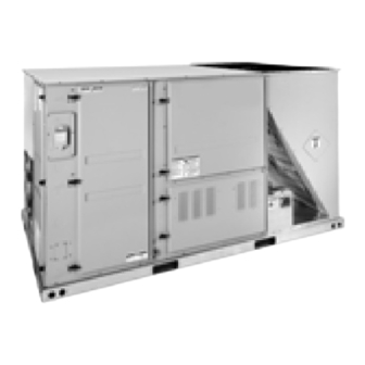
J**ZR SERIES W/SMART EQUIPMENT™
3 - 5 Ton
60 Hertz
General . . . . . . . . . . . . . . . . . . . . . . . . . . . . . . . . . . . . . . . . . . . . . 2
Installation . . . . . . . . . . . . . . . . . . . . . . . . . . . . . . . . . . . . . . . . . . . 5
Preceding Installation . . . . . . . . . . . . . . . . . . . . . . . . . . . . . . . . 5
Limitations. . . . . . . . . . . . . . . . . . . . . . . . . . . . . . . . . . . . . . . . 6
Location . . . . . . . . . . . . . . . . . . . . . . . . . . . . . . . . . . . . . . . . . . . 7
Rigging And Handling . . . . . . . . . . . . . . . . . . . . . . . . . . . . . . . . 7
Ductwork . . . . . . . . . . . . . . . . . . . . . . . . . . . . . . . . . . . . . . . . . 15
Side Panels . . . . . . . . . . . . . . . . . . . . . . . . . . . . . . . . . . . . . . . 16
Condensate Drain . . . . . . . . . . . . . . . . . . . . . . . . . . . . . . . . . . 16
Compressors . . . . . . . . . . . . . . . . . . . . . . . . . . . . . . . . . . . . . . 16
Filters . . . . . . . . . . . . . . . . . . . . . . . . . . . . . . . . . . . . . . . . . . . . 17
Power And Control Wiring . . . . . . . . . . . . . . . . . . . . . . . . . . . . 17
Optional Electric Heat . . . . . . . . . . . . . . . . . . . . . . . . . . . . . . . 27
Optional Gas Heat . . . . . . . . . . . . . . . . . . . . . . . . . . . . . . . . . . 28
Options/Accessories . . . . . . . . . . . . . . . . . . . . . . . . . . . . . . . . 30
Economizer Sequences . . . . . . . . . . . . . . . . . . . . . . . . . . . . . . 31
Dry Bulb Changeover . . . . . . . . . . . . . . . . . . . . . . . . . . . . . . . 31
Single Enthalpy Changeover . . . . . . . . . . . . . . . . . . . . . . . . . . 31
Dual Enthalpy Changeover . . . . . . . . . . . . . . . . . . . . . . . . . . . 31
Auto . . . . . . . . . . . . . . . . . . . . . . . . . . . . . . . . . . . . . . . . . . . . . 31
1 JA3 thru A5ZR Unit Limitations . . . . . . . . . . . . . . . . . . . . . . . . 7
2 Weights and Dimensions . . . . . . . . . . . . . . . . . . . . . . . . . . . . . 8
3 JA3 thru A5ZR Unit Accessory Weights . . . . . . . . . . . . . . . . . 8
4 JA3 thru A5ZR Unit Physical Dimensions . . . . . . . . . . . . . . . 11
5 JA3 thru A5ZR Unit Clearances . . . . . . . . . . . . . . . . . . . . . . 11
6 Side Duct Dimensions . . . . . . . . . . . . . . . . . . . . . . . . . . . . . . 13
7 Left/End Duct Dimensions . . . . . . . . . . . . . . . . . . . . . . . . . . . 14
8 Control Wire Sizes . . . . . . . . . . . . . . . . . . . . . . . . . . . . . . . . . 19
9 Electrical Data . . . . . . . . . . . . . . . . . . . . . . . . . . . . . . . . . . . . 20
10 Physical Data . . . . . . . . . . . . . . . . . . . . . . . . . . . . . . . . . . . . . 24
11 Electric Heat Minimum Supply Air . . . . . . . . . . . . . . . . . . . . . 27
12 Gas Pipe Sizing - Capacity of Pipe . . . . . . . . . . . . . . . . . . . . 28
13 Gas Heat Minimum Supply Air . . . . . . . . . . . . . . . . . . . . . . . 29
14 Smart Equipment™ Economizer Board Details . . . . . . . . . . 33
15 Supply Air Limitations . . . . . . . . . . . . . . . . . . . . . . . . . . . . . . 36
16 Altitude/Temperature Correction Factors . . . . . . . . . . . . . . . 38
17 JA3 thru A5ZR Side Duct Application . . . . . . . . . . . . . . . . . . 40
1 Unit Shipping Bracket . . . . . . . . . . . . . . . . . . . . . . . . . . . . . . . 5
2 Condenser Covering . . . . . . . . . . . . . . . . . . . . . . . . . . . . . . . . 5
3 Compressor Section . . . . . . . . . . . . . . . . . . . . . . . . . . . . . . . . 5
4 Component Location (JA3ZR Shown) . . . . . . . . . . . . . . . . . . 6
5 Unit 4 Point Load Weight . . . . . . . . . . . . . . . . . . . . . . . . . . . . 8
6 Unit 6 Point Load Weight . . . . . . . . . . . . . . . . . . . . . . . . . . . . 8
7 Center of Gravity . . . . . . . . . . . . . . . . . . . . . . . . . . . . . . . . . . 8
8 JA3ZR Physical Dimensions . . . . . . . . . . . . . . . . . . . . . . . . . 9
9 JA4 thru A5ZR Physical Dimensions . . . . . . . . . . . . . . . . . . 10
10 JA3 thru A5ZR Unit Bottom Duct Openings . . . . . . . . . . . . . 12
11 JA3 thru A5ZR Unit Electrical Entry . . . . . . . . . . . . . . . . . . . 13
12 JA3 thru A5ZR Unit Side Duct Openings . . . . . . . . . . . . . . . 13
13 JA3 thru A5ZR Unit Left/End Duct Opening . . . . . . . . . . . . . 14
14 JA3 thru A5ZR Roof Curb . . . . . . . . . . . . . . . . . . . . . . . . . . . 14
15 JA3 thru A5ZR Transition Roof Curb . . . . . . . . . . . . . . . . . . 15
16 Side Duct Connection . . . . . . . . . . . . . . . . . . . . . . . . . . . . . . 15
17 Return Panel In Place For Side Duct Conversion . . . . . . . . 16
TABLE OF CONTENTS
Free Cooling Operation . . . . . . . . . . . . . . . . . . . . . . . . . . . . . . 31
Power Exhaust . . . . . . . . . . . . . . . . . . . . . . . . . . . . . . . . . . . . 32
Airflow Performance . . . . . . . . . . . . . . . . . . . . . . . . . . . . . . . . . . . 40
Air Balance . . . . . . . . . . . . . . . . . . . . . . . . . . . . . . . . . . . . . . . 42
Checking Air Quantity . . . . . . . . . . . . . . . . . . . . . . . . . . . . . . . 42
Operation . . . . . . . . . . . . . . . . . . . . . . . . . . . . . . . . . . . . . . . . . . . 46
Cooling Sequence Of Operation . . . . . . . . . . . . . . . . . . . . . . . 46
Cooling Operation Errors . . . . . . . . . . . . . . . . . . . . . . . . . . . 46
Reheat Mode Sequence Of Operation . . . . . . . . . . . . . . . . . . 48
Electric Heating Sequence Of Operations. . . . . . . . . . . . . . . . 49
Electric Heat Operation Errors . . . . . . . . . . . . . . . . . . . . . . . 49
Gas Heating Sequence Of Operations . . . . . . . . . . . . . . . . . . 50
Gas Heating Operation Errors . . . . . . . . . . . . . . . . . . . . . . . 50
Start-Up (Cooling) . . . . . . . . . . . . . . . . . . . . . . . . . . . . . . . . . . . . 51
Start-Up (Gas Heat) . . . . . . . . . . . . . . . . . . . . . . . . . . . . . . . . . . . 52
Checking Gas Heat Input . . . . . . . . . . . . . . . . . . . . . . . . . . . . . . . 52
Charging The Unit . . . . . . . . . . . . . . . . . . . . . . . . . . . . . . . . . . . . 55
Control Board Navigation Components . . . . . . . . . . . . . . . . . . . . 55
Start-Up Sheet . . . . . . . . . . . . . . . . . . . . . . . . . . . . . . . . . . . . . . . 65
LIST OF TABLES
18 JA3 thru A5ZR Bottom Duct Application . . . . . . . . . . . . . . . . 41
19 RPM Selection . . . . . . . . . . . . . . . . . . . . . . . . . . . . . . . . . . . 42
20 Indoor Blower Specifications . . . . . . . . . . . . . . . . . . . . . . . . . 42
21 Power Exhaust Specifications . . . . . . . . . . . . . . . . . . . . . . . . 42
22 Motor Sheave Datum Diameters . . . . . . . . . . . . . . . . . . . . . . 44
23 Additional Static Resistance . . . . . . . . . . . . . . . . . . . . . . . . . 45
24 Electric Heat Limit Setting . . . . . . . . . . . . . . . . . . . . . . . . . . . 49
25 Electric Heat Anticipator Setpoints . . . . . . . . . . . . . . . . . . . . 49
26 Gas Heat Anticipator Setpoints . . . . . . . . . . . . . . . . . . . . . . . 51
27 Gas Rate Cubic Feet Per Hour . . . . . . . . . . . . . . . . . . . . . . . 53
28 Gas Heat Stages . . . . . . . . . . . . . . . . . . . . . . . . . . . . . . . . . . 54
29 Smart Equipment™ UCB Details . . . . . . . . . . . . . . . . . . . . . 56
32 JA3ZR Charging Table . . . . . . . . . . . . . . . . . . . . . . . . . . . . . 63
33 JA4ZR Charging Table . . . . . . . . . . . . . . . . . . . . . . . . . . . . . 63
34 JA5ZR Charging Table . . . . . . . . . . . . . . . . . . . . . . . . . . . . . 64
LIST OF FIGURES
18 Supply Panel In Place For Side Duct Conversion . . . . . . . . 16
19 Save Side Panels For Economizer Hood Tops . . . . . . . . . . 16
20 Condensate Drain . . . . . . . . . . . . . . . . . . . . . . . . . . . . . . . . 16
21 Field Wiring Disconnect . . . . . . . . . . . . . . . . . . . . . . . . . . . . 18
22 Typical Low Voltage Field Wiring . . . . . . . . . . . . . . . . . . . . . 19
23 Side Entry Gas Piping . . . . . . . . . . . . . . . . . . . . . . . . . . . . . 28
24 Bottom Entry Gas Piping . . . . . . . . . . . . . . . . . . . . . . . . . . . 28
25 SE-ECO1001-0 Economizer Controller . . . . . . . . . . . . . . . . 33
26 Belt Adjustment . . . . . . . . . . . . . . . . . . . . . . . . . . . . . . . . . . 36
27 Altitude/Temperature Correction Factors . . . . . . . . . . . . . . . 38
28 Dry Coil Delta P . . . . . . . . . . . . . . . . . . . . . . . . . . . . . . . . . . 43
29 Reheat Operation Piping Schematic . . . . . . . . . . . . . . . . . . 48
30 Cooling Operation Piping Schematic . . . . . . . . . . . . . . . . . . 48
31 Typical Flame . . . . . . . . . . . . . . . . . . . . . . . . . . . . . . . . . . . . 55
32 Typical Two Stage Gas Valve . . . . . . . . . . . . . . . . . . . . . . . 55
33 Typical Single Stage Gas Valve . . . . . . . . . . . . . . . . . . . . . . 55
34 Unit Control Board . . . . . . . . . . . . . . . . . . . . . . . . . . . . . . . . 56
5566229-JIM-B-1019
Advertisement
Table of Contents

Related Manuals for Johnson Controls J ZR Series


Summary of Contents for Johnson Controls J ZR Series
-
Page 1: Table Of Contents
R-410A J**ZR SERIES W/SMART EQUIPMENT™ 3 - 5 Ton 60 Hertz TABLE OF CONTENTS General ..........2 Free Cooling Operation . -
Page 2: General
5566229-JIM-B-1019 General Johnson Controls JA3-A5ZR units are single package air conditioners with optional gas heating designed for outdoor Before performing service or maintenance operations on installation on a rooftop or slab and for non-residential use. unit, turn off main power switch to unit. Electrical shock These units can be equipped with factory or field installed could cause personal injury. - Page 3 Renewal Parts As soon as a unit is received, it should be inspected for possible For authorized replacement parts call Johnson Controls, Inc. damage during transit. If damage is evident, the extent of the National Source 1 Parts outlet 1-866-523-9670.
- Page 4 5566229-JIM-B-1019 Nomenclature ® 3-5 Ton J**ZR Johnson Controls Model Number Nomenclature JA3 ZR C A 2 A 1 Product Generation Nominal Cooling Capacity 2 = Second Generation JA3 = 3 Ton JA4 = 4 Ton Cabinet Options JA5 = 5 Ton...
-
Page 5: Installation
230v and 415v power supply respectively. Change Figure 1: Unit Shipping Bracket tap on transformer for 208-3-60 or 380-3-50 operation. See unit wiring diagram. Turn each bracket toward the ground and the protective plywood covering will drop to the ground. Johnson Controls Ducted Systems... -
Page 6: Limitations
Side entry power maintain warm, comfortable and control wiring temperature Compressor access Slide-out drain pan knockouts with 1" NPT Intelligent control board connection for safe and efficient Toolless door operation latch Figure 4: Component Location (JA3ZR Shown) Johnson Controls Ducted Systems... -
Page 7: Location
Installer must make provisions for adequate LENGTH OF FORKS MUST BE A MINIMUM OF 60 INCHES. combustion and ventilation air in accordance with section 5.3 of Air for Combustion and Ventilation of the National Fuel Gas Johnson Controls Ducted Systems... -
Page 8: Weights And Dimensions
Unit Accessory Shipping Operating Economizer Power Exhaust Electric Heat Gas Heat 1. Weight given is for the maximum heater size available (24KW). 2. Weight given is for the maximum number of tube heat exchangers available (8 tube). Johnson Controls Ducted Systems... -
Page 9: Ja3Zr Physical Dimensions
5566229-JIM-B-1019 29.75 15.51 29.52 59.00 Ø 25.31 See detail A for gas inlet 11 3/8 See detail B for drain location LEFT 4 3/16 FRONT 21 3/16 27 5/16 Figure 8: JA3ZR Physical Dimensions Johnson Controls Ducted Systems... -
Page 10: Ja4 Thru A5Zr Physical Dimensions
59.00 15.38 Ø 24.47 TYP. 2 PL. See detail A for gas inlet 11 3/8 See detail B for drain location LEFT 4 3/16 FRONT 21 3/16 27 5/16 Figure 9: JA4 thru A5ZR Physical Dimensions Johnson Controls Ducted Systems... -
Page 11: Ja3 Thru A5Zr Unit Physical Dimensions
1. Units must be installed outdoors. Over hanging structure or shrubs should not obscure condenser air discharge outlet. 2. Units may be installed on combustable floors made from wood or class A, B or C roof covering materials. Johnson Controls Ducted Systems... -
Page 12: Ja3 Thru A5Zr Unit Bottom Duct Openings
Bottom condensate drain 14 1/2 25 9/16 Bottom gas supply entry 16 3/8 18 1/16 FRONT Bottom power, control and convenience outlet wiring entry 3X Ø 0.875 Ø 2.469 Figure 10: JA3 thru A5ZR Unit Bottom Duct Openings Johnson Controls Ducted Systems... -
Page 13: Side Duct Dimensions
Figure 12: JA3 thru A5ZR Unit Side Duct Openings Table 6: Side Duct Dimensions Dimension (in.) Unit Model Number JA3ZR 27 3/4 12 1/16 27 1/2 JA4ZR 27 3/4 12 1/16 27 1/2 JA5ZR 27 3/4 12 1/16 27 1/2 Johnson Controls Ducted Systems... -
Page 14: Left/End Duct Dimensions
JA4ZR 30.357 13.365 22.516 JA5ZR 30.357 13.365 22.516 RIGHT 80-5/8 INSULATED DECK UNDER CONDENSER SECTION SUPPLY RETURN 2 TYP. 50-1/2 INSULATED DECK UNDER COMPRESSOR SECTION FRONT 8 or 14 Figure 14: JA3 thru A5ZR Roof Curb Johnson Controls Ducted Systems... -
Page 15: Ductwork
Return shown with duct connection cover panel as with the painted surface DOWN, facing the bottom duct shipped. opening. The supply panel is secured with the bracket (already Johnson Controls Ducted Systems... -
Page 16: Side Panels
This type of oil is highly susceptible to moisture absorption. R-410A compressor lubricants are known to cause long term damage to some synthetic roofing materials. Figure 19: Save Side Panels For Economizer Hood Tops Johnson Controls Ducted Systems... -
Page 17: Filters
NEC and CEC as water or moisture cannot be drawn into the unit during specified above and/or local codes. normal operation. The above water-proofing conditions will also apply when installing a field supplied disconnect switch. Johnson Controls Ducted Systems... -
Page 18: Field Wiring Disconnect
Refer to Electrical Data Table 9 to size power or the basepan inside the curb. wiring, fuses, and disconnect switch. TERMINAL BLOCK TB1 FACTORY OR FIELD GROUND SUPPLIED DISCONNECT THREE PHASE POWER SUPPLY Figure 21: Field Wiring Disconnect Johnson Controls Ducted Systems... -
Page 19: Control Wire Sizes
R, RC, or RH. OCC is an output from the thermostat to indicate the Occupied X is an input to the thermostat to display Error Status condi ons. Figure 22: Typical Low Voltage Field Wiring Johnson Controls Ducted Systems... -
Page 20: Electrical Data
24.1 33.4 36.1 28.9 39.4 42.1 None 11.5 13.4 15.6 39.5 0.66 14.4 20.5 22.8 19.2 26.5 28.8 23.1 31.4 33.6 1. Minimum Circuit Ampacity. 2. Dual Element, Time Delay Type. 3. HACR type per NEC. Johnson Controls Ducted Systems... - Page 21 29.5 24.1 34.4 37.1 28.9 40.4 43.1 None 10.1 11.9 13.9 16.1 39.5 0.66 14.4 23.3 19.2 29.3 23.1 31.9 34.1 1. Minimum Circuit Ampacity. 2. Dual Element, Time Delay Type. 3. HACR type per NEC. Johnson Controls Ducted Systems...
- Page 22 39.6 42.4 28.9 45.6 48.4 None 13.7 15.5 18.4 20.6 39.5 0.66 14.4 25.5 27.8 19.2 31.5 33.8 23.1 36.4 38.6 1. Minimum Circuit Ampacity. 2. Dual Element, Time Delay Type. 3. HACR type per NEC. Johnson Controls Ducted Systems...
- Page 23 35.8 24.1 40.6 43.4 28.9 46.6 49.4 None 14.1 15.9 18.9 21.1 39.5 0.66 14.4 28.3 19.2 34.3 23.1 36.9 39.1 1. Minimum Circuit Ampacity. 2. Dual Element, Time Delay Type. 3. HACR type per NEC. Johnson Controls Ducted Systems...
-
Page 24: Physical Data
10.56 Rows Fins per inch Tube diameter 0.375 0.375 0.375 Refrigerant control REHEAT COIL DATA Face area (Sq. Ft.) 7.78 7.78 7.78 Rows Fins per inch Tube diameter 0.375 0.375 0.375 Refrigerant control Solenoid Solenoid Solenoid Johnson Controls Ducted Systems... - Page 25 4 - (24 x 16 x 4) 1. JA3ZR, JA4ZR, JA5ZR have crankcase heaters standard. 2. 2 In. Throwaway, Standard, MERV (Minimum Efficiency Reporting Value) 3. 3. 2 In. Pleated, Optional, MERV 8. 4. 4 In. Pleated, Optional, MERV 13. Johnson Controls Ducted Systems...
- Page 26 10.56 Rows Fins per inch Tube diameter 0.375 0.375 0.375 Refrigerant control REHEAT COIL DATA Face area (Sq. Ft.) 7.78 7.78 7.78 Rows Fins per inch Tube diameter 0.375 0.375 0.375 Refrigerant control Solenoid Solenoid Solenoid Johnson Controls Ducted Systems...
-
Page 27: Optional Electric Heat
208/230-3-60 1020 1000 460-3-60 600-3-60 208/230-3-60 1280 1420 1400 1400 460-3-60 1400 1400 1400 1400 600-3-60 1400 1400 1400 208/230-3-60 1600 1600 1600 1600 1600 460-3-60 1600 1600 1600 1600 1600 600-3-60 1600 1600 1600 1600 Johnson Controls Ducted Systems... -
Page 28: Optional Gas Heat
NOTE: There may be a local gas utility requirement specifying a minimum diameter for gas piping. All units require a 3/4 inch pipe connection at the entrance fitting. Line should not be sized smaller than the entrance fitting size. Johnson Controls Ducted Systems... -
Page 29: Gas Heat Minimum Supply Air
Check all joints for leaks with soap solution or other material suitable for the purpose. NEVER USE A FLAME. All LP gas equipment must conform to the safety standards of the National Fire Protection Association. Johnson Controls Ducted Systems... -
Page 30: Options/Accessories
These heaters mount in the heat compartment with the instructions included with the outdoor air hood to complete the heating elements extending into the supply air chamber. All the assembly. Field installed Motorized Outdoor Damper accessories include complete instructions for installation. Johnson Controls Ducted Systems... -
Page 31: Economizer Sequences
The economizer dampers continue to Four types of free cooling options are available: dry bulb modulate to control the supply air temperature to the changeover, single enthalpy, dual enthalpy changeover, and Economizer Setpoint. Auto. Johnson Controls Ducted Systems... -
Page 32: Power Exhaust
De-energizes exhaust fan when economizer output is If the demand for cooling from the space/return is satisfied, the below the Economizer Damper Position for Exhaust Fan economizer output will modulate to minimum position and the Johnson Controls Ducted Systems... -
Page 33: Smart Equipment™ Economizer Board Details
Negative of the SA BUS communication Common for SA BUS power and circuit to the UCB. Through the unit wiring harness, may continue communication circuits on to the 4-stage board and/or fault detection & diagnostics board Johnson Controls Ducted Systems... - Page 34 24V~ IN Pin connections at right on upper edge of economizer board 24 VAC common connection to power the economizer board. 24 VAC transformer Common referenced to Connects through circuit traces to C/COM terminals and pins cabinet ground distributed on the economizer board. Johnson Controls Ducted Systems...
- Page 35 Connects through circuit trace to 24V~ IN pin HOT sensor BldgPres parameter reports input status (-.250-.250”/w/-.062- BLDG 0-5 VDC positive input from the Building .062kPa). Used for modulating power exhaust functions when PRES Pressure sensor ExFType selection is Modulating Damper or Variable Frequency Fan. Johnson Controls Ducted Systems...
-
Page 36: Supply Air Limitations
Blower Rotation Check for proper supply air blower rotation. If the blower is rotating backwards, the line voltage at the unit point of power connection is misphased (See ‘PHASING’). Figure 26: Belt Adjustment Johnson Controls Ducted Systems... - Page 37 Table 16 and Figure 27. tension at least two times during the first 24 hours of operation. Any retensioning should fall between the min. and max. deflection force values. 5. After adjusting re-tighten nuts (A). Johnson Controls Ducted Systems...
-
Page 38: Altitude/Temperature Correction Factors
This value must be corrected for elevation. Example 2: A system, located at 5,000 feet of elevation, is to deliver 1,400 CFM at a static pressure of 1.5". Use the unit BHP at 5,000 ft. = 0.7 x .832 = 0.58 Johnson Controls Ducted Systems... - Page 39 0.00 0.00 0.00 0.02 0.02 0.02 1100 0.04 -0.02 0.03 0.01 0.01 0.01 0.02 0.02 0.02 1200 0.04 0.00 0.04 0.01 0.01 0.01 0.02 0.02 0.02 1300 0.03 0.01 0.05 0.01 0.01 0.01 0.03 0.03 0.03 Johnson Controls Ducted Systems...
-
Page 40: Ja3 Thru A5Zr Side Duct Application
1. Blower performance includes gas heat exchangers and 2” filters. See STATIC RESISTANCE table for additional applications. 2. See RPM SELECTION table to determine desired motor sheave setting and to determine the maximum continuous BHP. 3. kW = BHP x 0.932. Johnson Controls Ducted Systems... -
Page 41: Ja3 Thru A5Zr Bottom Duct Application
1. Blower performance includes gas heat exchangers and 2” filters. See STATIC RESISTANCE table for additional applications. 2. See RPM SELECTION table to determine desired motor sheave setting and to determine the maximum continuous BHP. 3. kW = BHP x 0.932. Johnson Controls Ducted Systems... -
Page 42: Air Balance
Tighten blower pulley and motor sheave set screws after Remove the dot plugs from the duct panel (for location of any adjustments. Re-check set screws after 10-12 hrs. run the dot plugs see Figures 12 and 13). time is recommended. Johnson Controls Ducted Systems... -
Page 43: Dry Coil Delta P
Determine the number of turns the variable motor sheave is open. 0.45 JA4ZR JA5ZR 0.35 0.25 JA3ZR 0.15 0.05 1000 1500 2000 2500 3000 3500 Air ow (CFM) Figure 28: Dry Coil Delta P Johnson Controls Ducted Systems... -
Page 44: Motor Sheave Datum Diameters
CFM. Adjustments of the blower speed and belt tension are REQUIRED. Verify proper sheave alignment; tighten blower pulley and motor sheave set screws after these adjustments. Re-checking set screws after 10-12 hrs. run time is recommended. Johnson Controls Ducted Systems... -
Page 45: Additional Static Resistance
3. The pressure drop through the economizer is greater for 100% outdoor air than for 100% return air. If the resistance of the return air duct is less than 0.25 IWG, the unit will deliver less CFM during full economizer operation. Johnson Controls Ducted Systems... -
Page 46: Operation
• Source 1 P/N S1-JC-MAP1810-OP economizer. The dampers will modulate to maintain a constant • MAP Gateway Quick Start Guide P/N 24-10737-16 supply air temperature as monitored by the discharge air sensor. • MAP Gateway Instruction P/N 24-10737-8 Johnson Controls Ducted Systems... - Page 47 Low ambient mode operates the compressors in this manner: thermostat setting higher than the conditioned space 10 minutes on, 5 minutes off. The indoor blower is operated temperature and raising the dehumidistat setting higher than the conditioned space humidity. Johnson Controls Ducted Systems...
-
Page 48: Reheat Mode Sequence Of Operation
--------> --------> Cond. Cond. --------> Coil Coil --------> Coil 1 Coil 2 HGRH Valve OPEN SOL #3 Recovery Valve SOL #1 Suc on Discharge CLOSED Comp. Recovery Valve SOL #2 Figure 30: Cooling Operation Piping Schematic Johnson Controls Ducted Systems... -
Page 49: Electric Heating Sequence Of Operations
Refer to Table 25 for the required electric heat anticipator setting, for electronic thermostats refer to thermostat manufacturer’s installation instructions. Table 25: Electric Heat Anticipator Setpoints SETTING, AMPS 0.13 Johnson Controls Ducted Systems... -
Page 50: Gas Heating Sequence Of Operations
Any time the UCB senses voltage at the GV without a call for one-hour period for unsafe conditions. heat for a continuous five-minute period, the UCB will lock-on the indoor blower and a flash code is initiated (Table 31). When Johnson Controls Ducted Systems... -
Page 51: Start-Up (Cooling)
Turn unit electrical power on. “W1” is lost. Set the room thermostat fan switch to on. Check indoor blower rotation. • If blower rotation is in the wrong direction. Refer to Phasing Section in general information section. Johnson Controls Ducted Systems... -
Page 52: Start-Up (Gas Heat)
2 or a 1 cubic foot test dial. Using the number of seconds it takes for one revolution of the dial, calculate the cubic feet of gas consumed per hour. (See example below). Johnson Controls Ducted Systems... -
Page 53: Gas Rate Cubic Feet Per Hour
Manifold pressure adjustment procedure. Turn off all power to the unit. Using the outlet pressure port on the gas valve, connect a manometer to monitor the manifold pressure. Remove plastic cap covering the pressure adjustment screw. Johnson Controls Ducted Systems... -
Page 54: Gas Heat Stages
Remove the screws holding each end of the manifold to the manifold supports. Disconnect wiring to the gas valves and spark igniter(s). Remove the manifold & gas valve assembly. Orifices can now be inspected and/or replaced. To service burners, complete step 4. Johnson Controls Ducted Systems... -
Page 55: Charging The Unit
For more information on the Smart Equipment™ unit control board navigation, refer to the Smart Equipment™ Quick Start Guide. NOTE: For more in-depth sequence of operation of the Smart Equipment™ control, refer to the Smart Equipment™ Controls Sequence of Operation Overview LIT- 12011950. Johnson Controls Ducted Systems... -
Page 56: Smart Equipment™ Ucb Details
Connects through circuit trace to the thermostat connection 24 VAC hot for switched inputs to the UCB strip R terminal, right FAN OVR pin, right HPS1 pin, right HPS2 pin, lower DFS pin and lower APS pin Johnson Controls Ducted Systems... - Page 57 Supply Air Temperature sensor input from 10KΩ with open circuit. Used in heat/cool staging cutouts, free cooling SAT+ @ 77°F, Type III negative temperature coefficient operation, demand ventilation operation, comfort ventilation thermistor operation, economizer loading operation, VAV cooling operation, hydronic heat operation. Johnson Controls Ducted Systems...
- Page 58 The VFD alarm contact switches from R within the unit wiring 24 VAC hot input from the normally open VFD VFDFLT harness. 24 VAC input results in unit shutdown and a “VFD alarm contact fault” alarm Johnson Controls Ducted Systems...
- Page 59 Lockout” and C1 output is then prevented until alarm reset. HPS2 24 VAC hot out for refrigerant circuit 2 High Not effective for one stage compressor UCBs. Connects (right pin) Pressure Switch through circuit trace to the R terminal Johnson Controls Ducted Systems...
- Page 60 4-way Joystick for display menu navigation Item USB connector at right of UCB Used for backup, restoration, & copying of board parameters as Type A female Universal Serial Bus connector well as board software updating through a flash drive Johnson Controls Ducted Systems...
- Page 61 2. We recommend 26 AWG solid, 6-wire (3 twisted pairs) cable as the best fit for fabricating modular cables with the modular jack housing assembly. Be sure the cable you use fits the modular jack housing. The preassembled cables that are available from Anixter (Part No. CBL-NETWORKxxx) use 24 gauge wire. Johnson Controls Ducted Systems...
-
Page 62: Cable For Fc Buses And Sa Buses In Order Of Preference . 61 31 Flash Codes For The Gas Heat Ignition Control Board
Verify that there is no wind, rain or snow entering the heat compartment to interfere with ignition or the burners. Verify that there are no conditioned air leaks or heat exchanger breaches to interfere with ignition or the burners Johnson Controls Ducted Systems... -
Page 63: Ja3Zr Charging Table
10.1 80/62 10.8 300 Cfm/Ton 10.1 80/67 10.8 300 Cfm/Ton 10.1 80/72 300 Cfm/Ton 10.1 75/63 10.8 400 Cfm/Ton 10.1 80/62 10.8 400 Cfm/Ton 10.1 80/67 10.9 400 Cfm/Ton 10.1 80/72 400 Cfm/Ton 10.1 75/63 10.8 Johnson Controls Ducted Systems... -
Page 64: Ja5Zr Charging Table
Liquid Liquid Delta T Compr. Indoor Db/Wb Pressure Temp. Pressure Temp. amps 300 Cfm/Ton 80/62 300 Cfm/Ton 80.000001/66.999999 300 Cfm/Ton 80/72 300 Cfm/Ton 75/62 400 Cfm/Ton 80/62 400 Cfm/Ton 80.000001/66.999999 400 Cfm/Ton 80/72 400 Cfm/Ton 75/62 Johnson Controls Ducted Systems... -
Page 65: Start-Up Sheet
5566229-JIM-B-1019 Start-Up Sheet Johnson Controls Ducted Systems... - Page 66 5566229-JIM-B-1019 Johnson Controls Ducted Systems...
- Page 67 5566229-JIM-B-1019 Johnson Controls Ducted Systems...
- Page 68 5566229-JIM-B-1019 Johnson Controls Ducted Systems...
- Page 69 5566229-JIM-B-1019 Johnson Controls Ducted Systems...
- Page 70 Subject to change without notice. Printed in U.S.A. 5566229-JIM-B-1019 Copyright © 2019 by Johnson Controls, Inc. All rights reserved. Supersedes: 5566229-JIM-A-0818 York International Corporation 5005 York Drive Norman, OK 73069...
Need help?
Do you have a question about the J ZR Series and is the answer not in the manual?
Questions and answers