
Related Manuals for Southern States EV-H


Summary of Contents for Southern States EV-H
- Page 1 Type EV-H Aluminum Vertical Break Disconnect Switch All Ratings INSTALLATION & INSTRUCTION MANUAL...
- Page 2 Page I The Quality Name in High Voltage Switching...
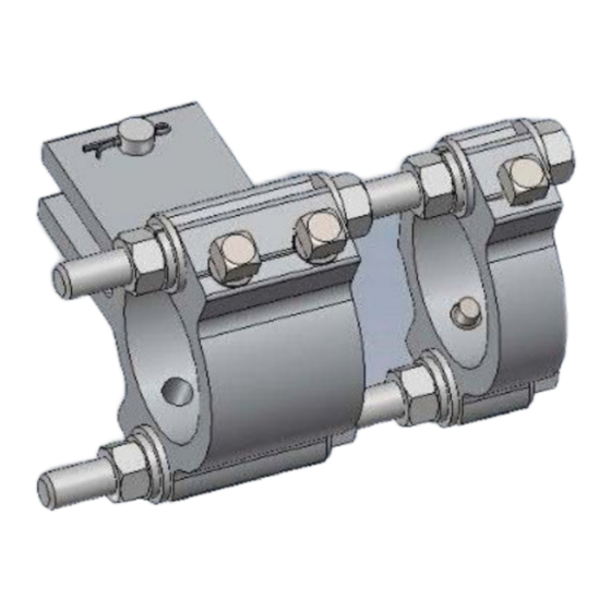
- Page 3 ATTENTION: Southern States will begin supplying a portion of new operating mechanism designs with Rapid-Set clevises for orders designed after 9/1/23. If your Operating Mechanism print calls for Rapid-Set clevises (see image below for an example), please utilize the instructions on the following pages for all linkage adjustments.
- Page 4 Please scan or use the link below for video instructions of Rapid-Set. Southern States Rapid Set Instructions S T E P 1 : Install the auxiliary arm by aligning the straight edge of the arm with the center of the vertical pipe and bolting it into place using two of the provided mounting holes.
- Page 5 S T E P 2 : Install the adjustable arm with the radius “R” set to the recommended length provided in the operating mechanism drawings. S T E P 3 : Install the auxiliary arm Rapid-Set clevis and drive pipe. Ensure that roughly 12” of pipe extends beyond the adjustable arm clevis connection so that the pipe makes contact with the adjustable arm in the position shown.
- Page 6 S T E P 4 : With the auxiliary arm properly aligned with the vertical pipe and the switch phase in the full closed position, pierce the pipe at both ends. NOTE: U-bolt style clevises require pre-drilling on all pipes thicker than SCH40.
- Page 7 S T E P 6 : After the drive phase is adjusted to operate correctly, set all phases to full closed, and install the interphase pipe following the procedure below. For switches driven by the center phase: a. With the interphase pipe centered and all clevises in place, pierce the interphase pipe at the locations shown.
- Page 8 For switches driven by one of the end phases: a. With the interphase pipe centered and all clevises in place, pierce the interphase pipe with at the locations shown. Do not remove plastic caps at this time. b. Adjust the timing of the center phase by adjusting the length “L” of the Rapid-Set clevis attached to the drive phase.
- Page 9 c. Set the timing of the last phase by adjusting the length “L” of the Rapid-Set clevis attached to the last phase. S T E P 7 : With all the phases adjusted, open and close the three phase assembly and inspect for proper operation. Once adjustments are finalized, pierce all remaining connections (switch operator, adjustable arm, etc).
- Page 10 Please ensure that you are using the latest installation and maintenance instructions. If you do not understand any part of these instructions or need assistance, contact Southern States Service Division at 770-946-4562 during normal business hours (8:00am – 4:30pm EST, M-F) or 770-...
- Page 11 The purchaser (“Purchaser”) of certain Equipment (the “Equipment”) identified in the Instruction Manual accompanying these Terms of Use sold by Southern States, LLC (“Southern States”), by Purchaser’s acceptance or Use of Equipment in any way, agrees to the Terms of Use set forth below (the word “Use” herein means receipt, testing, inspection, installation, operation, maintenance and otherwise handling the Equipment): •...
- Page 12 The Quality Name in High Voltage Switching LIMITED WARRANTY Southern States, LLC (“SSLLC”) warrants only to the Warranty Holder (hereinafter defined as the “End User” or the “Immediate Purchaser”, as applicable, pursuant to the terms and conditions of this Limited Warranty as set forth below), that the Product identified below will, upon shipment, be free of defects in workmanship and material for the applicable Warranty Period.
- Page 13 Page V The Quality Name in High Voltage Switching Type EV-H Aluminum Vertical Break Disconnect Switch All Ratings...
-
Page 14: Table Of Contents
Page VI The Quality Name in High Voltage Switching Table of Contents Chapter Page Summary & Introduction ........................1 Important ............................1 Summary ............................1 Introduction ............................ 2 Recommended Tools & Values ...................... 3 Product Description ........................... 4 Receiving, Handling & Storage ......................5 Receiving &... - Page 15 Table 2: Recommended Installation & Maintenance Table .............. 16 Figures Page Figure 1: Typical EV-H Disconnect Switch Terminology ..... Error! Bookmark not defined. Figure 2: Match-Marked Components ....................6 Figure 3: Contact Blade Centered Among Contact Fingers ............... 7 Figure 4: Evenly Distributed Contact Pressure .................. 8 Figure 5: Blade Tip Travel .........................
-
Page 16: Summary & Introduction
The sales contract contains the entire obligation of Southern States. The Warranty contained in the contract between the parties is the sole warranty of Southern States. Any statements contained herein do not create new warranties or modify the... -
Page 17: Introduction
The instructions contained within this manual are necessary for the safe installation, maintenance, and operation of the EV-H switch. A qualified person, familiar with this of type equipment, should carefully read and follow the instructions. -
Page 18: Recommended Tools & Values
Page 3 of 17 Summary & Introduction Recommended Tools & Values Table 1: Recommended Tools & Torque Values Recommended Tools Recommended Torque Values Type Sizes Bolt/Nut size Torque (ft-lb) Hand Wrenches and/or 15/16”, 3/4", 1/2” Sockets 5/8”, 9/16” Drill Bit 1/4”... -
Page 19: Product Description
Page 4 of 17 Product Description Product Description Figure 1: Typical EV-H Disconnect Switch Terminology A – Hinge Terminal Pad F – Jaw Contact Fingers K – Control Arm B – Crank Arm G – Arcing Horn (Optional) L – Bearing C –... -
Page 20: Receiving, Handling & Storage
Storage All components of the EV-H vertical break disconnect switch are suitable for outdoor use and do not have any special storage requirements. If a motor operator is furnished be sure to connect the heater circuit, using the provided external wiring, while the unit is in storage. -
Page 21: Installation & Adjustment Procedures
Page 6 of 17 Installation & Adjustment Procedures Installation & Adjustment Procedures In general, installing a disconnect switch consists of the following: • Mounting insulators to switch base • Mounting live parts to insulators • Mounting switch base to structure •... -
Page 22: Contact Adjustment
Page 7 of 17 Installation & Adjustment Procedures 1.6.1. After properly installing the rotating insulator, mount the stationary hinge end insulator. Confirm that it is parallel to rotating insulator and shim as necessary. 1.6.2. Once the hinge insulators are aligned, do not readjust them. Any contact alignment adjustments will be made to the jaw insulator. - Page 23 Page 8 of 17 Installation & Adjustment Procedures 2.1.2. All contact fingers must be in contact with the blade tip as shown in Figure 4. If necessary, loosen the jaw mounting bolts and rotate the jaw against the bolt hole tolerances to achieve even contact distribution along the length of the blade tip.
-
Page 24: Optional Accessories
Page 9 of 17 Installation & Adjustment Procedures Figure 6: Blade Tip Alignment in Jaw 2.1.6. Energize the switch only after a final inspection of all five of these conditions for proper contact. 3. Optional Accessories 3.1. Arcing Horns (if equipped): 3.1.1. -
Page 25: Mounting Disconnect Switch Onto The Structure
Operating Mechanism drawing. See Table 1 for torque spec. 4.6. Conventional blade open positions are shown in Figure 9. The EV-H switch will be shipped with one of these blade open angles unless another angle is specified. Slight changes to the blade fully open angles can be made in the field. Adjust the open position stop bolt on the bearing assembly shown in Figure 10 as necessary. -
Page 26: Operating Mechanism
Page 11 of 17 Installation & Adjustment Procedures Figure 10: Open Position Blade Stop 4.7. Mount the conductors to both ends of the switch pole before final adjustments. Conductor loads can alter fine switch alignment. Final adjustments should not be performed prior to connecting the conductors. -
Page 27: Switch Adjustments (Tuning)
Page 12 of 17 Installation & Adjustment Procedures 5.4 To aid switch inspection from the ground, there will be at least one threader bolt (piercing bolt) on every Operating Mechanism. They may be installed, in most cases, on the bottom sides of the clevises so they can be viewed from the ground when pinned. - Page 28 Page 13 of 17 Installation & Adjustment Procedures that the operating mechanism only exerts enough force to toggle the blade tip perpendicular to the jaw contacts. Excess downward force on the blade could result in damage to the switch that will render it inoperable.
- Page 29 Page 14 of 17 Installation & Adjustment Procedures Refer to Figure 14. 6.4.2. Set the adjustable arm to the preliminary setting specified on the Operating Mechanism drawing, adjustment may be necessary to achieve proper operation. 6.4.3. Be sure that all the lower bearing stops have been loosened to prevent binding during test operations.
- Page 30 Page 15 of 17 Installation & Adjustment Procedures 6.4.4.2. Return the switch to almost the closed position, but not toggled. 6.4.4.3. Match-mark the adjustable arm and the pipe clevis 6.4.4.4. Loosen the bolts on the adjustable arm and pipe clevis 6.4.4.5.
-
Page 31: Recommended Inspection Maintenance
Page 16 of 17 Recommended Inspection Maintenance Recommended Inspection Maintenance Southern States disconnect switches are designed to operate with minimum maintenance. While disconnecting switches are not readily serviced at frequent intervals, periodic inspection is important for satisfactory operation and maximized overall life. Frequency of inspection and maintenance depends on the installation site, weather, atmospheric conditions, experience of operating personnel, and any special operation requirements. -
Page 32: Patrolling Inspection (6 Months)
Page 17 of 17 Recommended Inspection Maintenance Patrolling Inspection (6 Months) The patrolling inspection is a largely visual inspection on an energized unit in service. The frequency of the inspection is determined by the local conditions and policies of the owner of the equipment. •... - Page 33 Discover Additional Vertical Break Switches from Southern States: 30 Georgia Avenue Hampton, Georgia 30228 Phone: 770-946-4562 Fax: 770-946-8106 E-mail: support@southernstatesllc.com http://www.southernstatesllc.com ©2022 Southern States IB-101-EVH-72.5-R0 06092022 Printed U.S.A.
Need help?
Do you have a question about the EV-H and is the answer not in the manual?
Questions and answers