Table of Contents
Advertisement
Quick Links
Advertisement
Table of Contents

Subscribe to Our Youtube Channel
Summary of Contents for SystemAir ZRS Series
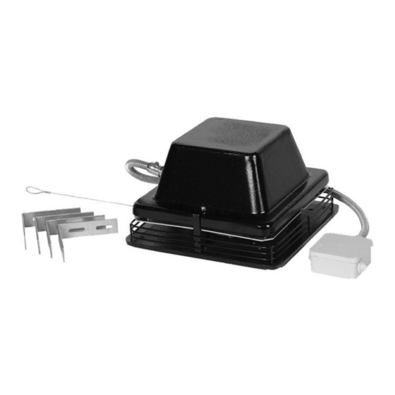
- Page 1 Installation, Operation and Maintenance instruction ZRS Smoke gas fan...
-
Page 2: Table Of Contents
Table of contents 1 Introduction ............1 13 EU Declaration of Conformity........ 14 Product description ........1 14 UK Declaration of Conformity........ 15 Intended use ..........1 Document description........1 Product overview......... 1 Name plate ..........1 1.5.1 Type designation ......2 Product liability.......... -
Page 3: Introduction
10. Serial number: part number/production number/produc- tion date 11. IP class, enclosure class 12. Current, A 13. Voltage, V Use a mobile device to scan the scannable code and go to the Systemair documentation portal for more documentation and document translations. -
Page 4: Type Designation
Product liability Note: Systemair is not liable for damages that the product causes in these conditions: Information that is necessary in a given situation. • The product is incorrectly installed, operated or maintained. -
Page 5: Personal Protective Equipment
capabilities, or lack of experience and knowledge, unless Transportation and they have been given supervision or instruction. storage • Do not allow children to play with the device. Warning Personal protective Make sure that the product does not equipment become damaged or wet during transportation. -
Page 6: Installation
Cut a hole in the insulation carpet. Make sure that the Installation hole has the same dimension as the inlet cone of the fan. To do before the installation of the product • Use installation material with fire resistance rating for the installation location. -
Page 7: Electrical Connection
Push the fan and steering rods into the chimney. It is not Electrical connection necessary to attach the fan with screws in the chimney, the steering rods keeps the fan in position. To do before the electrical connection • Make sure that the electrical connection agrees with the product specification on the motor name plate. -
Page 8: Commissioning
Set the installed speed controller in the OFF position. Refer to the instruction manual for the installed speed The commissioning report is found at www.systemair.com. controller. Set the installed safety switch in the OFF position. -
Page 9: Maintenance
• Do not clean the product with steel brushes or sharp objects. • Always use spare parts from Systemair. • Do not bend the fan impeller blades. • To find spare parts, refer to the scannable code on the name plate. -
Page 10: Troubleshooting
Troubleshooting Note: If you cannot find a solution to your problem in this section, speak to Systemair technical support. Problem Cause Solution The fan impeller is not correctly Speak to Systemair technical support. balanced. There is dirt on the fan impeller. -
Page 11: Disposal
For warranty claims, send a written maintenance plan and product or the packaging of the product shows that this the commissioning report to Systemair. The warranty is only product is not domestic waste. The product must be recycled applicable for these conditions: at an approved disposal location for electrical and electronic •... -
Page 12: Technical Data
12.1 Technical data overview Max. temperature of transported air, °C Max. ambient temperature, °C Refer to the data sheet in the online catalogue at www.systemair.com. Sound pressure, dB IP class Voltage, current, frequency, enclosure Refer to the name plate. Refer to 1.5 Name plate... -
Page 13: Wiring Diagrams
12.3 Wiring diagrams Abbreviation in wiring diagram Cable colour Yellow Blue White Green Brown Black Grey Green/Yellow 12.3.1 Wiring diagrams for ZRS fans ZRS fans 1–phase 230 V ZRS 170–180 12.3.2 Wiring diagrams for speed controller for AC motors Note: The selection of electrical accessories must be done in line with the technical parameters of the product. - Page 14 REE — Thyristor REE 1 and REE 2 - Surface mounting or with flush mounting casing included. REE 4 - Surface mounting. Note: Starting currents must be considered when you select the speed controller type. Products that are used with this speed controller must have a built-in overheating protec- tion and must be designed for thyristor speed control.
- Page 15 Relay connection. There is always 230 V between ~ and D. Fan N when the transformer knob is in one of the positions Thermostat 1–5. Motor protection. If the motor protection is not in use, Tk Mains supply must be looped together. C.
-
Page 16: Eu Declaration Of Conformity
EU Declaration of Conformity We, the manufacturer Manufacturer Systemair Sverige AB Address Industrivägen 3 739 30 Skinnskatteberg Sweden declare under our sole responsibility that the products Machine Smoke gas fan Type/Model fulfils the relevant provisions of following directives and RoHS Directive 2011/65/EU and amendment (EU) 2015/... -
Page 17: Declaration Of Conformity
UK Declaration of Conformity We, the manufacturer Manufacturer Systemair Sverige AB Address Industrivägen 3 SE-73930 Skinskatteberg Sweden declare under our sole responsibility that the products Machine Smoke gas fan Type/Model fulfils the relevant provisions of following directives and EN IEC 63000:2018... - Page 18 © Copyright Systemair AB All rights reserved Systemair AB reserves the rights to alter their products without notice. This also applies to products already ordered, as long as it does not affect the previously agreed specifications. Document in original language...


Need help?
Do you have a question about the ZRS Series and is the answer not in the manual?
Questions and answers