
Related Manuals for Godex AG4000T


Summary of Contents for Godex AG4000T
- Page 1 AG4000T USER MANUAL AG-4000-400001, AG-4000-600001 AG4000T (print & apply system) User Manual: AG4000T Version: 1.1 draft (needs revision) Issue Date: April 2021 Godex AG4000T User Manual Page 1 of 42...
-
Page 2: Table Of Contents
2 Introduction ..........................4 2.1 Overview ..........................4 2.2 Applicator Specifications Summarized ................4 2.3 Dimensions AG4000T – 400 mm .................... 5 2.4 Dimensions AG4000T – 600 mm .................... 6 3 Basic Safety Precautions ......................7 3.1 Coverage ..........................7 3.2 Following the instructions in this operating manual ............. - Page 3 8.2 Operation modes ........................ 31 8.3 Inputs and Outputs ......................32 8.3.1 Outputs .......................... 33 8.3.2 Inputs ..........................34 9 Maintenance ..........................35 Annex 1 ZX1000i printer GPIO (General Purpose Input Output) module functions ..36 Godex AG4000T User Manual Page 3 of 42...
-
Page 4: Introduction
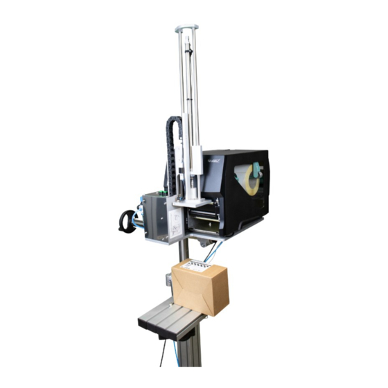
The AG4000T applies the last printed label to the product, what enables you to attach unique information to each single product coming down the production - or packaging line. -
Page 5: Dimensions Ag4000T - 400 Mm
2.3 Dimensions AG4000T – 400 mm Pic. 2 Pic. 3 Pic. 5 Pic. 4 Godex AG4000T User Manual Page 5 of 42... -
Page 6: Dimensions Ag4000T - 600 Mm
2.4 Dimensions AG4000T – 600 mm Pic. 6 Pic. 7 Pic. 8 Pic. 9 Godex AG4000T User Manual Page 6 of 42... -
Page 7: Basic Safety Precautions
Safety rules and instructions either written or referred to in this manual apply to the installation, the usage and the maintenance of both the applicator- and the printer components within AG4000T systems. They do however not replace any safety instruction published in separate Godex ZX1000(X)i user- and service manuals, and must be considered complementary to those instead. -
Page 8: Occupational Health And Safety Rules
The legibility of safety signs, symbols and notices on the device must be maintained at all times. In the event of damage and/or illegibility, any such signs must be restored by the device’s keeper to their original condition. Godex AG4000T User Manual Page 8 of 42... -
Page 9: Never
3.8 Applied harmonized standards and the safe use of electrical appliances AG4000T Print & Apply systems are class I electrical devices in terms of the necessary protection against electric shock in accordance with harmonized standard EN 61140, ed. -
Page 10: The Possible Risks Of Electric Shocks If Working With The Applicator
(e.g. the piston) can be stopped by hand without the use of excessive force (max. 150N) The customer shall bear responsibility for any adjustments that are not made by the equipment manufacturer prior to delivery. Godex AG4000T User Manual Page 10 of 42... -
Page 11: Contents Of Delivery - What's In The Box
ZX1200i (203 DPI), 250 mm effective stroke AG4000T with standard 100x100mm applicator head and standard stand to guide you through the installation and make you familiar with the usage of the AG4000T print & apply solution. Further in this manual you find an option list. -
Page 12: Box 2: Applicator Unit Components
1 x set screw ?? Pic. 19 1 x alarm beacon set (optional) Pic. 21 Depending on the configuration you have ordered there might be slightly different contents, please check with your local Godex Partner Pic. 15 Pic. 14 Pic. 13 Pic. 16 Pic. -
Page 13: Box 3: Stand Components
The illustration below show the stand configuration used for this example. Your Particular application may be different, but the principles are the same. Pic. 22 In the box you will find assembly kit for the standard stand. Pic. 25 Pic. 24 Pic. 23 Godex AG4000T User Manual Page 13 of 42... -
Page 14: Assembling The System
Let the narrow ends of the screw holes face each other on the inside whilst mounting the feet. Pic. 30 The height of each foot is adjustable individually to level the stand on uneven surfaces Pic. Pic. 30 Pic. 31 Pic. 29 Godex AG4000T User Manual Page 14 of 42... - Page 15 Firmly connect the three legs with screws Pic. 34 and Pic. 35. Pic. 34 Pic. 35 Take the remaining profile (Pic. 36) and mount it firmly with screws onto the central profile: Pic. 36 Pic. 37 Pic. 38 Godex AG4000T User Manual Page 15 of 42...
- Page 16 At a later stage the end of the tube must be inserted in - and firmly attached to clamp on the applicator by tightening the screw Pic. 47. Pic. 47 Pic. 46 Godex AG4000T User Manual Page 16 of 42...
-
Page 17: Installing The Internal Rewinder And Gpio Card In The Printer
Remove the plastic cap (Pic. 48) Remove the left cover (Pic. 49) Pic. 48 Pic. 49 6. Insert the bearing (Pic. 50) 7. Insert the bearing (Pic. 51) Pic. 50 Pic. 51 Godex AG4000T User Manual Page 17 of 42... - Page 18 19. Install clutch kit. (Pic. 55). The torque setting from the factory of the clutch is suitable for the AG4000T application. In case the torque setting would need to be adjusted at some point, please refer to the printer service manual.
- Page 19 (Pic. 61). 23. Reinstall the left cover (Pic. 62) 24.-25. Open the printer door and reinstall the screws (Pic. 63) Pic. 61 Pic. 63 Pic. 62 Godex AG4000T User Manual Page 19 of 42...
-
Page 20: Installing The Label Dispensing Edge
5.4 Installing the label dispensing edge Remove the bottom right cover/panel. (If you needed to complete steps in Paragraph 5, start from Pic. Pic. 65 Pic. 64 Pic. 66 Pic. 67 Pic. 68 Pic. 69 Godex AG4000T User Manual Page 20 of 42... - Page 21 70, install the air valve and tube to the dispensing edge Pic. 72. Fix the dispensing edge with the screws Pic. 74. Pic. 70 Pic. 71 Pic. 73 Pic. 72 Pic. 74 Godex AG4000T User Manual Page 21 of 42...
-
Page 22: Assembling The Applicator Unit
Pic. 78 and Pic. 79. Fix the applicator unit to the base plate with screws from the bottom side Pic. 80. Pic. 78 Pic. 79 Pic. 77 Pic. 80 Godex AG4000T User Manual Page 22 of 42... - Page 23 Connect the support air valve to the air pipe from the applicator unit. Applicator system assembly is completed and you can mount the unit onto the stand, for this particular example configuration refer to Pic. 47. Pic. 83 Godex AG4000T User Manual Page 23 of 42...
-
Page 24: Applicator Unit Adjustments. Fine Tuning
In order to adjust this distance, you need to open the printer door Pic. 84 loosen the 4 screws holding the applicator head Pic. 85, set the right distance Pic. 86 and retighten the screws. Loosen the screws Pic. 85 Pic. 84 Pic. 86 Godex AG4000T User Manual Page 24 of 42... -
Page 25: Adjusting The Applicator Head Vertical Resting Position
Adjust the height Pic. 88 Retighten the counter nut Pic. 89 Pic. 87 Pic. 88 You can adjust the height of the applicator head by turning piston rod Pic. 89 Counter nut Godex AG4000T User Manual Page 25 of 42... -
Page 26: Adjusting The Support Air Angle And Pressure
By turning the rod you can change the support air angle With the knob of the valve, you can adjust the pressure Pic. 91 Pic. 92 Recommended support air angle (particular applications might require different setting) Godex AG4000T User Manual Page 26 of 42... -
Page 27: Operating Your Ag4000T
4. Switch on the main switch on the back of the printer. Pic. 93 5. Push the power button beneath the printer display Pic. 95 Pic. 94 Pic. 93 Pic. 95 Godex AG4000T User Manual Page 27 of 42... -
Page 28: Setting The Printer To The Right Gpio Mode And Applicator Setting Lock
“Lock” the setting Pic. 99. This “Lock” will set printer to applicator mode independent on the setting coming with the label format. Confirm with OK button Pic. 100. The Smart Backfeed function should be turned off. Pic. 99 Pic. 100 Pic. 101 Godex AG4000T User Manual Page 28 of 42... -
Page 29: Creating Label Format And Loading Media
Load the printer with suitable media and TTR if applicable. The printer is ready to go now. For more information regarding creating labels and handling the ZX printer, please refer to the printer user manual. Godex AG4000T User Manual Page 29 of 42... -
Page 30: Connecting To Auxiliary Systems
Pic. 106. The chosen Ethernet is just a random example of how data can be exchanged between printer and such auxiliary system. Examples how to connect the AG4000T applicator unit to the most common kinds of auxiliary systems, starting with the auxiliary system as a triggering device are explained below. -
Page 31: Operation Modes
Pic. 110 Direct / Trigger mode toggle. See in Pic. 110 red circled area. If the jumper is on, the direct mode is active, if there is no jumper, trigger mode is active. Godex AG4000T User Manual Page 31 of 42... -
Page 32: Inputs And Outputs
PLC built in a robot, a PLC ultimately controlled by an ERP system, et cetera. Below is the diagram of the GPIO of the AG4000T general inputs and outputs. The two connectors (DB9 and DB15) are on the left side of the machine, see Pic. 111. -
Page 33: Outputs
8.3.1 Outputs DB9 provide error output that can be used for signaling errors. Pic. 113 DB15 Provides additional outputs such as Data Ready, Ready, Home position. Pic. 114 Godex AG4000T User Manual Page 33 of 42... -
Page 34: Inputs
8.3.2 Inputs DB15 provide inputs for triggering devices. ! Important ! The Applicator unit should be in Trigger Mode Pic. 115 Godex AG4000T User Manual Page 34 of 42... -
Page 35: Maintenance
9 Maintenance AG4000T systems require hardly any maintenance, which goes for both the printer and the applicator components. For applicator maintenance instructions please see the “AG4000T Maintenance & Options Guide” and for printer maintenance instructions the “ZX1200i Service Manual”. Both are made available to authorized GoDEX dealers... -
Page 36: Annex 1 Zx1000I Printer Gpio (General Purpose Input Output) Module Functions
4 inputs: START PRINT (trigger), FEED, PAUSE, REPRINT 5 outputs: SERVICE REQUIRED, END PRINT (printing), MEDIA OUT, RIBBON OUT, DATA READY +24 V internal printer Voltage (can be used to power e.g. sensor) GND Godex AG4000T User Manual Page 36 of 42... - Page 37 (sensor, button, etc.). Isolated with external power is recommended when external voltage will be used for inputs (PLC’s, etc.), in this case, external power source should be connected to PIN’s 1, 2 and accordingly configured Jumpers. Godex AG4000T User Manual Page 37 of 42...
- Page 38 Printjob in printers buffer No Printjob in printers buffer (Counter = xxx on LCD) (Ready on LCD) PIN 4 -> GND PIN 4 -> GND 1 Label is Feed 1 Label is Feed Godex AG4000T User Manual Page 38 of 42...
- Page 39 When in pause mode, the Feed signal is activated kept L for more than 3 secs, printer buffer is cleared (all printjobs in the printer are deleted), same as holding the front Feed button. After print buffer is cleared, printer returns automatically to Ready state. Godex AG4000T User Manual Page 39 of 42...
- Page 40 PIN 3 -> GND PIN 3 -> GND Last printed label is Last printed label is printed printed Godex AG4000T User Manual Page 40 of 42...
- Page 41 Outputs: Service required (PIN10): H->L when there is any kind of error. End print (PIN11): Pulse when printing is finished. The timing diagrams of this output are dependent on the selected Mode. Godex AG4000T User Manual Page 41 of 42...
- Page 42 Mode 3 ^XSET,APPLICATOR,0,3 Mode 4 ^XSET,APPLICATOR,0,4 Check Media (PIN12): Check Ribbon (PIN13): Data Ready (PIN14): H->L when there is media error. H->L when there is ribbon error. H->L when data is in the buffer Godex AG4000T User Manual Page 42 of 42...
Need help?
Do you have a question about the AG4000T and is the answer not in the manual?
Questions and answers