Table of Contents
Advertisement
Quick Links
I N S T A L L A T I O N I N S T R U C T I O N S
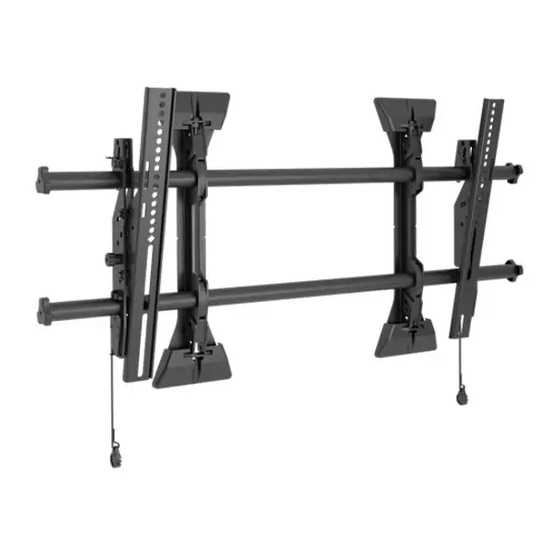
(Standard three-upright configuration shown for each model.
Configuration will vary based on application)
TILD1X3NE1-M
TILD1X4NE1-M
TILD1X5NE1-M
TILD1X4NE1-R
TILD1X5NE1-R
TILD1X3NE1-L
TILD1X3NE1-R
TILVAB2
Accessory
TILD1X4NE1-L
TILD1X5NE1-L
Nanolumens LED Wall Mounts / Accessory
Spanish Product Description
German Product Description
Portuguese Product Description
Italian Product Description
Dutch Product Description
French Product Description
TILD1xXNE1 Series
Advertisement
Table of Contents

Related Manuals for LEGRAND CHIEF TILD1 XNE1 Series


Summary of Contents for LEGRAND CHIEF TILD1 XNE1 Series
- Page 1 I N S T A L L A T I O N I N S T R U C T I O N S (Standard three-upright configuration shown for each model. Configuration will vary based on application) TILD1X3NE1-M TILD1X4NE1-M TILD1X5NE1-M TILD1X4NE1-R TILD1X5NE1-R TILD1X3NE1-L...
-
Page 2: Important Safety Instructions
See figure below for examples. product. The information contained in this document is subject to change without notice or obligation of any kind. Legrand TILD1X4NE1 shown (example) makes no representation of warranty, expressed or implied, regarding the information contained herein. - Page 3 TILD1xXNE1 Series Installation Instructions LEGEND Tighten Fastener Pencil Mark Apretar elemento de fijación Marcar con lápiz Befestigungsteil festziehen Stiftmarkierung Apertar fixador Marcar com lápis Serrare il fissaggio Segno a matita Bevestiging vastdraaien Potloodmerkteken Serrez les fixations Marquage au crayon Loosen Fastener Drill Hole Aflojar elemento de fijación Perforar...
-
Page 4: Tools Required For Installation
Installation Instructions TILD1xXNE1 Series TOOLS REQUIRED FOR INSTALLATION Level [4+ ft. long] 7/32" [Small level] 3/8" 1/2" String [Laser level] 3/4" deep Ratchet with well socket 7/16" drive PARTS Mounting Hardware Kit (Qty per bag) TiLD1XxNE1 Hardware Kit# (Qty per bag) *-(1x3/1x4/1x5) B (2) [UX10x60R anchor]... -
Page 5: Pre-Installation
Installation Instructions TILD1xXNE1 Series INSTALLATION bottom row. This determines to which end (top or bottom) the vertical connector brackets are attached. Preinstallation Just a tip - IMPORTANT ! : Reference the LED screen installation For larger LED walls it is helpful to manual for specific instructions regarding care, handling, check placement and alignment of the mounts by cabling and installation of the LED screens. -
Page 6: Back View
TILD1xXNE1 Series Installation Instructions Determining Installation Site Hold spacer plate (P) up to wall, lining up keyhole slot with line drawn in Step 2. (See Figure 3) IMPORTANT ! : The top of the LED screen is 5.5" above NOTE: This line will indicate the center line for the location of the the center line of the mounting lags in the upper mounting spacers used to mount the video wall uprights. - Page 7 Installation Instructions TILD1xXNE1 Series Adding Vertical Connector Kit (Sold Separately) Hang left upright (L) onto side of spacer plate (P) using screws loosely installed in Step 6. NOTE: If more LED screens will need to be added to the top or Tighten Phillips undercut machine screws (Q) to secure left bottom of the screen configuration, add TILVAB2 upright (L) to spacer plate (P).
- Page 8 TILD1xXNE1 Series Installation Instructions Installing First Mount to Wall Drill two pilot holes (see Table 1 for size) at each location marked in Step 2 (See Figure 8) and follow fastener The TILD1X3NE1 / TILD1X4NE1 /TILD1X5NE1 LED wall information located in Table 1. mounts are designed to be mounted to the following wall types: IMPORTANT ! : Refer to Fastener Installation Methods Table 1: Fastener Information...
- Page 9 Installation Instructions TILD1xXNE1 Series Place a level across front of the mount at bottom of leveling 11. Check the level of the mount horizontally at the bottom of slots. (See Figure 11) the leveling slots and vertically on the side of the uprights. (See Figure 12) and (See Figure 13) Check the level of the mount at the bottom of the leveling slots.
- Page 10 TILD1xXNE1 Series Installation Instructions Adding Additional Uprights Hang spacer plate (P) onto lower screws installed in (TILD1X3NE1 shown) previous section on middle upright (M). (See Figure 15) Tighten both screws (Q) to secure spacer plate (P) to (Q) x 2 middle upright (M).
- Page 11 Installation Instructions TILD1xXNE1 Series Hold the adjustment washers in place by hand and tighten the fasteners at the top of the mount. 10. Drill lower pilot holes at attachment locations and use same tighten fasteners used at top of mount. 11.
- Page 12 TILD1xXNE1 Series Installation Instructions Position spacer plate (P) between uprights (L, M or N) middle upright (M) between mounting holes. (See Figure 23.62 inches 21.96 inches Use four 1/4-20 x 1/2" Phillips flathead screws (Q) to secure (middle to middle) (middle to right) uprights (L, M or N) to each other.
- Page 13 Installation Instructions TILD1xXNE1 Series [TILD1X4NE1 shown as example] Circles indicate tapping screw hole locations for attaching string to assist with alignment of mounts. Use locations nearest depth adjustment points for best results. Use locations nearest depth adjustment points for best results. adjust until depth of each upright touches string far right and far left...
- Page 14 TILD1xXNE1 Series Installation Instructions Adjustments Depth Adjust (Micro-adjust) The depth of each wall mount section is controlled by the screw Depth Adjust (Macro-adjust) in the mounting button, accessible only after removing LED IMPORTANT ! : Depth should be adjusted prior to display from LED housing.
- Page 15 Installation Instructions TILD1xXNE1 Series Installing Housings and LED Screens Fastener Installation Methods IMPORTANT ! : Reference the LED screen installation IMPORTANT ! : See Table 1 for appropriate hardware manual for specific instructions regarding care, handling, and pilot hole sizes for various wall types. cabling and installation of the LED housings and screens.
- Page 16 TILD1xXNE1 Series Installation Instructions Site Requirements for Wood or Plywood-backed Steel Stud *Steel stud ONLY If back side of wall is unfinished, drywall must be installed to a minimum of one stud left and right of the stud(s) being used 16"...
- Page 17 Installation Instructions TILD1xXNE1 Series DIMENSIONS-TILD1X3NE1 FRONT VIEW A BARE 8" CONCRETE OR 8"X8"X16" CONCRETE BLOCK WALL; OR A 3/4" THICKNESS PLYWOOD-BACKED, 2" X 4" WOOD STUDS (16" ON CENTER MINIMUM) WALL WITH A MAXIMUM DRYWALL THICKNESS OF 5/8"; OR A 3/4" THICKNESS PLYWOOD-BACKED, STEEL STUD WALL COVERED WITH DRYWALL HAVING A MAXIMUM THICKNESS OF 5/8"...
- Page 18 TILD1xXNE1 Series Installation Instructions DIMENSIONS-TILD1X4NE1 FRONT VIEW A BARE 8" CONCRETE OR 8"X8"X16" CONCRETE BLOCK WALL; OR A 3/4" THICKNESS PLYWOOD-BACKED, 2" X 4" WOOD STUDS (16" ON CENTER MINIMUM) WALL WITH A MAXIMUM DRYWALL THICKNESS OF 5/8"; OR A 3/4" THICKNESS PLYWOOD-BACKED, STEEL STUD WALL COVERED WITH DRYWALL HAVING A MAXIMUM THICKNESS OF 5/8"...
- Page 19 Installation Instructions TILD1xXNE1 Series DIMENSIONS-TILD1X5NE1 FRONT VIEW A BARE 8" CONCRETE OR 8"X8"X16" CONCRETE BLOCK WALL; OR A 3/4" THICKNESS PLYWOOD-BACKED, 2" X 4" WOOD STUDS (16" ON CENTER MINIMUM) WALL WITH A MAXIMUM DRYWALL THICKNESS OF 5/8"; OR A 3/4" THICKNESS PLYWOOD-BACKED, STEEL STUD WALL COVERED WITH DRYWALL HAVING A MAXIMUM THICKNESS OF 5/8"...
- Page 20 TILD1xXNE1 Series Installation Instructions...
- Page 21 Installation Instructions TILD1xXNE1 Series...
- Page 22 TILD1xXNE1 Series Installation Instructions...
- Page 23 Installation Instructions TILD1xXNE1 Series...
-
Page 24: Installation Instructions
F +31 (0) 495 580 845 Asia Pacific A Office No. 918 on 9/F, Shatin Galleria 8800-003383 Rev00 18-24 Shan Mei Street 2023 Legrand | AV Fotan, Shatin, Hong Kong www.legrandav.com P 852 2145 4099 05/2023 F 852 2145 4477...
Need help?
Do you have a question about the CHIEF TILD1 XNE1 Series and is the answer not in the manual?
Questions and answers