
Related Manuals for Pickering 41-180


Summary of Contents for Pickering 41-180
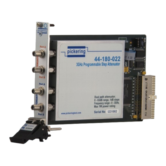
- Page 1 User Manual 3GHz Programmable Step Attenuator Module (Model No. 41-180) Issue 4.1 May 2017 pickeringtest.com pickering 3GHz PROGRAMMABLE STEP ATTENUATOR 41-180 Page (1)
- Page 2 © COPYRIGHT (2017) PICKERING INTERFACES. ALL RIGHTS RESERVED. No part of this publication may be reproduced, transmitted, transcribed, translated or stored in any form, or by any means without the written permission of Pickering Interfaces. Technical details contained within this publication are subject to change without notice.
- Page 3 Pickering Interfaces strives to fulfil all relevant environmental laws and regulations and reduce wastes and releases to the environment. Pickering Interfaces aims to design and operate products in a way that protects the environment and the health and safety of its employees, customers and the public. Pickering Interfaces endeavours to develop and manufacture products that can be produced, distributed, used and recycled, or disposed of, in a safe and environmentally friendly manner.
-
Page 4: Product Safety
If this product is heavy reference should be made to the safety instructions for provisions of lifting and moving. STATIC SENSITIVE To indicate that static sensitive devices are present and handling precautions should be followed. REED RELAY MODULE 40-110/115/120/125 3GHz PROGRAMMABLE STEP ATTENUATOR 41-180 Page (IV) Page (IV) -
Page 5: Table Of Contents
Pre Operation Checks ............3.1 Hardware Installation ............3.2 Software Installation .............3.2 Section 4 Programming Guide ..............4.1 Programming Options For Pickering PXI Cards....4.1 Programming The Module ............4.3 Using Pickering Drivers in LabVIEW ........4.4 Programmable Attenuator Soft Front Panel .......4.5 Section 5 Connector Information ..............5.1 Section 6 Trouble Shooting .................6.1... - Page 6 THIS PAGE INTENTIONALLY BLANK 3GHz PROGRAMMABLE STEP ATTENUATOR 41-180 Page (VI)
-
Page 7: Warnings And Cautions
Unused slots in the PXI/LXI chassis are populated with blanking plates to prevent access to user I/O signals that may be present. Blanking panels are available to order from Pickering in a variety of slot widths. If the product is not used in this manner for example by using an extender card then additional care must be taken to avoid contact with exposed signals. - Page 8 THIS PAGE INTENTIONALLY BLANK 3GHz PROGRAMMABLE STEP ATTENUATOR 41-180 Page (VIII)
- Page 9 63dB in 1dB steps. Attenuator operating time is typically just 5ms, ensuring fast setting times. The 41-180 Programmable Attenuator Module is ideal for The module is ideal for conditioning the signal levels from conditioning the output level of special to type sources, saving...
- Page 10 Attenuation Accuracy Versus Frequency With Attenuation Accuracy Versus Frequency With 8dB of Attenuation Set 32dB of Attenuation Set Attenuation Accuracy Versus Frequency With Attenuation Accuracy Versus Frequency With 48dB of Attenuation Set 63dB Set pickeringtest.com 3GHz PROGRAMMABLE STEP ATTENUATOR 41-180 Page 1.2...
- Page 11 RF Connectors: SMA, input and output connections are interchangeable. Versions with SMB connectors Mating Connectors & Cabling can be made available. For connection accessories for the 41-180 module please Contact Life (each pad): Typically 1x10 operations. 90-011D refer to the...
- Page 12 All modules are fully CE compliant and meet applicable EU Systems such as LabVIEW RT. For other RTOS support directives: Low-voltage safety EN61010-1:2001, contact Pickering. These drivers may be used with a variety of EMC Immunity EN61000-6-1:2001, Emissions EN55011:1998. programming environments and applications including: —...
-
Page 13: Technical Description
SECTION 2 - TECHNICAL DESCRIPTION FUNCTIONAL DESCRIPTION The 41-180 Programmable 0 to 63 dB Attenuator Module which forms part of the System 40 PXI RF Instrumentation range comprises either one or two independently programmable attenuators in a single width 3U PXI module. Each attenuator comprises seven attenuator pads ranging in value from 1 dB to 16dB. -
Page 14: Cascading Attenuators
The attenuation value is set via a soft panel which allows the operator to set the value using a sliding scale (which automatically switches-in the required attenuator pads), or manually switch-in the desired attenuator pads to set the value (refer to Figure 3.4). 3GHz PROGRAMMABLE STEP ATTENUATOR 41-180 Page 2.2... -
Page 15: Installation
Modular products require installation in a suitable PXI/LXI chassis. The module is designed for indoor use only. PREOPERATION CHECKS (UNPACKING) 1. Check the module for transport damage and report any damage immediately to Pickering Interfaces. Do not attempt to install the product if any damage is evident. -
Page 16: Hardware Installation
For a system comprising more than one chassis, turn ON the last chassis in the system followed by the penultimate, etc, and finally turn ON the external controller or chassis containing the system controller. 9. For Pickering Interfaces modular LXI installation there is no requirement to use any particular power up sequence. -
Page 17: Programming Guide
IVI Driver for Windows - pi40iv The pi40iv IVI (Interchangeable Virtual Instrument) driver supports all Pickering Interfaces PXI switch cards that are consistent with the Iviswtch class model - as are the great majority of cards in the System 40/45/50 ranges. It integrates well with LabWindows/CVI and LabVIEW, and is fully compatible with Switch Executive. - Page 18 Pickering LXI products include an SSH interface which allows remote command line access to control cards, or, using a suitable package, programmatic control. The user is advised to visit the Pickering web site for further details of all the above drivers, where documentation, example programs, and further help with driver choice are available.
-
Page 19: Programming The Module
Once the drivers are installed the manual “Sys40Prg.pdf” and driver help files which fully describes these functions can be found in the Pickering folder(s) or the Pickering entries on your Start Menu. The card must be opened before use and closed after using the following function calls: Direct Driver - Open with PIL_OpenCards or PIL_OpenSpecifiedCard and close with PIL_CloseCards or PIL_CloseSpecifiedCards respectively. -
Page 20: Using Pickering Drivers In Labview
USING PICKERING DRIVERS IN LabVIEW Most Pickering drivers include a LabVIEW wrapper to permit full operation of the Pickering product from the LabVIEW environment. These wrappers are normally installed to the current LabVIEW folder system during installation of the Pickering driver. -
Page 21: Programmable Attenuator Soft Front Panel
PROGRAMMABLE ATTENUATOR SOFT FRONT PANEL A dedicated Soft Front Panel application is available on the Pickering distribution disk and from the Pickering web- site. On the disk it can be found in the /Applications/Soft Front Panels/ folder, on the web-site it is located at: http://downloads.pickeringtest.info/downloads/Soft_Front_Panels/Programmable%20Attenuator%20v1.1.2.exe... - Page 22 SECTION 4 - PROGRAMMING GUIDE pickering THIS PAGE INTENTIONALLY BLANK 3GHz PROGRAMMABLE STEP ATTENUATOR 41-180 Page 4.6...
-
Page 23: Connector Information
SECTION 5 - CONNECTOR INFORMATION pickering SECTION 5 - CONNECTOR INFORMATION pickering PORT A PORT B PORT A PORT B Figure 5.1 - 41-180-022 Dual Programmable Attenuator Module: Connector Positions 3GHz PROGRAMMABLE STEP ATTENUATOR 41-180 Page 5.1... - Page 24 SECTION 5 - CONNECTOR INFORMATION pickering THIS PAGE INTENTIONALLY BLANK 3GHz PROGRAMMABLE STEP ATTENUATOR 41-180 Page 5.2...
-
Page 25: Trouble Shooting
PCI configuration, highlighting any potential configuration problems. Specific details of all installed Pickering switch cards are included. All the installed Pickering switch cards should be listed in the “Pilpxi information” section - if one or more cards is missing it may be possible to determine the reason by referring to the PCI configuration dump contained in the report, but interpretation of this information is far from straightforward, and the best course is to contact Pickering support: support@pickeringtest.com, if possible... - Page 26 SECTION 6 - TROUBLE SHOOTING pickering THIS PAGE INTENTIONALLY BLANK 3GHz PROGRAMMABLE STEP ATTENUATOR 41-180 Page 6.2...
-
Page 27: Maintenance Information
For PXI modules which are supported in one of Pickering Interfaces’ Modular LXI Chassis (such as the 60-102B and 60-103B) no module software update is required. If the module was introduced after the LXI chassis was manufactured the module may not be recognized, in this case the chassis firmware may need upgrading. -
Page 28: Calibration
VNA, set the VNA to measure S21 and observe the insertion loss at 3GHz. Insertion loss is stated at typically 3.6dB, this would not be expected to be more than 4.5dB Normalise the VNA plot to show 0dB loss with the through path selected on the 41-180 channel under test (0dB - no attenuator pads selected) Select each attenuator pad in turn. - Page 29 SECTION 7 - MAINTENANCE INFORMATION pickering Table 7.1 - Calibration Test Results For 41-180 Serial Number: Attenuator Chan: Date of Test: Operator’s Name: Test Equipment Used: Result Attenuator Measured Frequency Specification (delete as Path Attenuation appropriate) Thru path 3GHz <4.5dB...
- Page 30 SECTION 7 - MAINTENANCE INFORMATION pickering THIS PAGE INTENTIONALLY BLANK 3GHz PROGRAMMABLE STEP ATTENUATOR 41-180 Page 7.4...
Need help?
Do you have a question about the 41-180 and is the answer not in the manual?
Questions and answers