Table of Contents
Advertisement
Quick Links
309004
Rev B
CycleFlo II Pneumatic Pump Controller
Part No. 195265
120 psi (0.8 MPa, 8 bar) Maximum Air Working Pressure
Integrated Air Valves with Silenced Exhaust
Infinite Cycle Rate Adjustment Between 10 and 200 cpm
Standard 120 VAC Power
GRACO INC
P.O. BOX 1441
MINNEAPOLIS, MN 55440-1441
COPYRIGHT 1999, GRACO INC
Graco Inc. is registered to I.S. EN ISO 9001
Advertisement
Table of Contents

Related Manuals for Graco CycleFlo II


Summary of Contents for Graco CycleFlo II
- Page 1 Integrated Air Valves with Silenced Exhaust Infinite Cycle Rate Adjustment Between 10 and 200 cpm Standard 120 VAC Power GRACO INC P.O. BOX 1441 MINNEAPOLIS, MN 55440-1441 COPYRIGHT 1999, GRACO INC Graco Inc. is registered to I.S. EN ISO 9001...
-
Page 2: Table Of Contents
..........13 Graco Warranty.. -
Page 3: Warnings
Do not exceed the maximum working pressure of the lowest rated system component. • Route hoses away from traffic areas, sharp edges, moving parts, and hot surfaces. Do not expose Graco hoses to temperatures above 200 F (93 C) or below 0 F (-18 C). • Do not lift pressurized equipment. - Page 4 Fire, Explosion, and Electric Shock Hazard Improper grounding, poor air ventilation, open flames, or sparks can cause a hazardous condition and resulting fire or explosion and serious injury. • Ground the equipment. • Proper grounding dissipates static electricity generated in the equipment. •...
-
Page 5: General Description
General Description The CycleFlo II is a pneumatic pump controller that allows precise control over the cycle rate of the pump and therefor the flow rate. The pump cycle is initiated by a 120 volt signal. The pump cycle may be initiated by some other piece of equipment such as a timer or a pH controller. -
Page 6: Pneumatic Connections
Fig.1 - Electrical Diagrams Cycle Rate 120 Volt Adjustment Signal Relay Solenoid Valves Pneumatic Connections The integrated air valves, have a common air inlet (1/4" NPT) port and two outlet ports A and B (1/4” Tube) toward the front of the unit. The exhaust is silenced with a muffler. Do not exceed 120 psi at the air inlet to the unit. - Page 7 Husky 205. On pumps larger than the Husky 205, a three way solenoid valve (Graco Part Number 115606 or equivalent) MUST be installed on the main air supply to the pump. This ensures that pressure is not generated by the pump when the controller is not operating.
-
Page 8: Setup & Adjustment
One pump cycle consists of a momentary pressurization of each one of the two diaphragms. Adjustment The CycleFlo II comes with a cycle rate adjustment relay that can be adjusted using a screwdriver to control the Electric Shock Hazard energizing and deenergizing rate of the built-in solenoid valves. -
Page 9: Operation
Operation Priming the Pump Prime the pump by applying a 120 Volt signal to the controller to allow the temporary operation of the pump. This cycle rate may be increased or decreased to facilitate pump priming. Shut off electrical supply before making adjustments. -
Page 10: Parts
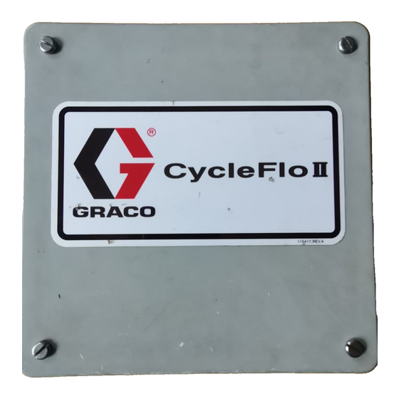
Parts Cycle rate adjustment relay Enclosure Air Solenoid Valves Part No. Description 115415 Enclosure 115417 Emblem (not shown – on front of unit) 115414 Cycle rate adjustment relay Air Solenoid Valves (Note: two valves are required per controller) 115418 Optional Accessories Part No. -
Page 11: Typical Installation Diagram
Typical Installation Diagram CycleFlo II Controller CycleFlo II Controller 110V on/off Isolation Relay Chemical (recommended) Injector Compressed Air In Control Signal (24VDC) 110 VAC Solenoid Solenoid Air Supply Valve #2 Valve #1 Solenoid Valve *Monitor / Controller Husky 1040 Metering Pump... -
Page 12: Technical Data
Typical Installation Diagram CycleFlo II Control ON/OFF signal (110VAC) Controller Compressed Air In Diaphragm Pump (Husky 205 shown) PH Controller, Flow Controller Timer, etc. sends 110 VAC on/off signal to CycleFlo II Flow Sensor Provided by others 9410A Technical Data Power Requirements: 120Vac, 50/60 Hz, .2A, 24W... -
Page 13: Mounting Hole Layout
Mounting Hole Layout All mounting tabs may be placed in 7 3/8” either position (187 mm) 5” 7 3/8” (127 mm) (187 mm) 5” (127 mm) 309004... -
Page 14: Graco Warranty
Graco, Graco will, for a period of twelve months from the date of sale, repair or replace any part of the equipment determined by Graco to be defective. This warranty applies only when the equipment is installed, operated and maintained in accordance with Graco's written recommendations.
Need help?
Do you have a question about the CycleFlo II and is the answer not in the manual?
Questions and answers