Graco Reactor 2 E-30 Repair Parts
Proportioning system
Hide thumbs
Also See for Reactor 2 E-30:
- Operation - repair - parts (116 pages) ,
- Repair and parts manual (114 pages) ,
- Repair parts (102 pages)
Table of Contents
Advertisement
Quick Links
Repair-Parts
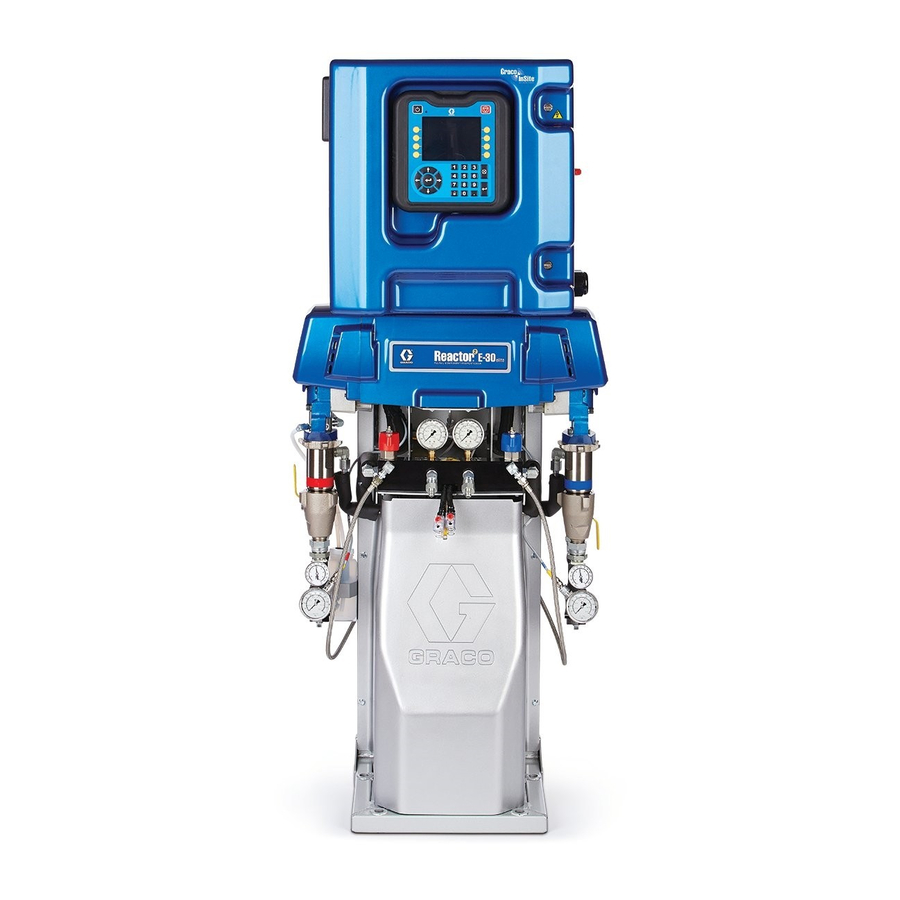
Reactor 2 E-30 and E-XP2
Proportioning System
Electric, Heated, Plural Component Proportioning System. For spraying polyurethane foam and
polyurea coatings. For professional use only. Not approved for use in explosive atmospheres or
hazardous locations.
Important Safety Instructions. Read all warnings and instructions in
this manual. Save these instructions.
PROVEN QUALITY. LEADING TECHNOLOGY.
333024A
EN
Advertisement
Table of Contents

Related Manuals for Graco Reactor 2 E-30


Summary of Contents for Graco Reactor 2 E-30
- Page 1 Repair-Parts Reactor 2 E-30 and E-XP2 Proportioning System 333024A Electric, Heated, Plural Component Proportioning System. For spraying polyurethane foam and polyurea coatings. For professional use only. Not approved for use in explosive atmospheres or hazardous locations. Important Safety Instructions. Read all warnings and instructions in this manual.
-
Page 2: Table Of Contents
Flush Inlet Strainer Screen ......46 Change Pump Lubricant ....... 47 Performance Charts..........92 Remove Pump..........48 Technical Specifications........95 Install Pump ..........49 Repair Drive Housing ........50 Graco Extended Warranty for Reactor® 2 Repair Electric Motor........53 Components ......... 97 333024A... -
Page 3: Warnings
Warnings Warnings The following warnings are for the setup, use, grounding, maintenance and repair of this equipment. The exclamation point symbol alerts you to a general warning and the hazard symbol refers to procedure-specific risks. When these symbols appear in the body of this manual refer back to these Warnings. Product-specific hazard symbols and warnings not covered in this section may appear throughout the body of this manual where applicable. - Page 4 Warnings WARNING SKIN INJECTION HAZARD High-pressure fluid from gun, hose leaks, or ruptured components will pierce skin. This may look like just a cut, but it is a serious injury that can result in amputation. Get immediate surgical treatment. • Do not spray without tip guard and trigger guard installed. •...
- Page 5 Warnings WARNING PRESSURIZED ALUMINUM PARTS HAZARD Use of fluids that are incompatible with aluminum in pressurized equipment can cause serious chemical reaction and equipment rupture. Failure to follow this warning can result in death, serious injury, or property damage. • Do not use 1,1,1-trichloroethane, methylene chloride, other halogenated hydrocarbon solvents or fluids containing such solvents.
- Page 6 Warnings WARNING MOVING PARTS HAZARD Moving parts can pinch, cut or amputate fingers and other body parts. • Keep clear of moving parts. • Do not operate equipment with protective guards or covers removed. • Pressurized equipment can start without warning. Before checking, moving, or servicing equipment, follow the Pressure Relief Procedure and disconnect all power sources.
-
Page 7: Important Isocyanate Information
Important Isocyanate Information Important Isocyanate Information Isocyanates (ISO) are catalysts used in two component materials. Isocyanate Conditions Keep Components A and B Separate Cross-contamination can result in cured Spraying or dispensing materials containing material in fluid lines which could cause serious isocyanates creates potentially harmful mists, injury or damage equipment. - Page 8 Important Isocyanate Information Foam Resins with 245 fa Blowing Changing Materials Agents NOTICE Some foam blowing agents will froth at temperatures Changing the material types used in your above 90°F (33°C) when not under pressure, equipment requires special attention to avoid especially if agitated.
-
Page 9: Models
Models Models Reactor 2 E-30 and E-30 Elite All elite systems include fluid inlet pressure and temperature sensors, Graco InSite , and Xtreme-Wrap 50 ft ™ (15 m) head hose. For part numbers, see Accessories, page 11 Base Model Elite Model... - Page 10 Models Reactor 2 E-XP2 and E-XP2 Elite All elite systems include fluid inlet pressure and temperature sensors, Graco InSite , and Xtreme-Wrap 50 ft ™ (15 m) head hose. For part numbers, see Accessories, page 11 Model Base Model Elite Model E–XP2, 15 kW...
-
Page 11: Approvals
24U315 Air Manifold Kit (4 outlets) Note 24U314 Wheel and Handle Kit Heated hoses provided with a system or sold 24T280 Graco InSite Kit individually are not approved by Intertek. 16X521 Graco InSite Extension cable 24.6 ft (7.5 m) 333024A... -
Page 12: Supplied Manuals
Manuals are also available at www.graco.com. Manual Description Reactor 2 E-30 and E-XP2 333023 Operation 333091 Reactor 2 E-30 and E-XP2 Startup Quick Guide 333092 Reactor 2 E-30 and E-XP2 Shutdown Quick Guide Related Manuals The following manuals are for accessories used with the Reactor. -
Page 13: Troubleshooting
QR code with your smartphone to be sent alarm needs to be directly to online troubleshooting for the active addressed immediately. error code. Otherwise, manually navigate to http://help.graco.com and search for the active Deviations A parameter critical error. to the process has... - Page 14 Troubleshooting Error Codes Note When an error occurs be sure to determine the code before resetting it. If you forget which error code occurred, see the Errors screen to view the last 200 errors, with date, time, and description. Error Location Type Description...
- Page 15 Troubleshooting Error Location Type Description Cause Solution A4NM High Motor Current Short circuit of Check wiring to the motor motor wiring. to ensure no bare wires are touching and that no wires are shorted to ground. Motor will not Remove pump gear rotate.
- Page 16 Troubleshooting Error Location Type Description Cause Solution A8DA Heater A No Current A Tripped circuit Visually check circuit breaker. breaker for a tripped condition. Loose/broken Check heater wiring for connection. loose wires. A8DB Heater B No Current B Tripped circuit Visually check circuit breaker.
- Page 17 Troubleshooting Error Location Type Description Cause Solution CACT TCM Communication Module does not Insert a system token into Error have software. the ADM module and cycle the power. Wait until the upload is complete before removing the token. No 24 VDC supply Green light on each module to module.
- Page 18 Troubleshooting Error Location Type Description Cause Solution EVCH Manual Hose Mode Manual hose mode Install a functioning fluid Enabled has been enabled temperature sensor (FTS) in System Setup on the hose. Manual hose screen. mode will automatically turn off. EAUX USB Busy USB drive has Do not remove USB drive...
- Page 19 Troubleshooting Error Location Type Description Cause Solution L1AX Low Chemical Level Low material level. Refill material and update drum level on ADM Maintenance screen. Alarm can be disabled on the System Setup screen. L1BX Low material level. Low Chemical Level Refill material and update drum level on ADM Maintenance screen.
- Page 20 Troubleshooting Error Location Type Description Cause Solution P0BX Pressure Imbalance Pressure Ensure material flow is B High difference between equally restricted on both A and B material material lines. is greater than the defined value. Ensure that the pressure Pressure imbalance is imbalance value, on the defined too low.
- Page 21 Troubleshooting Error Location Type Description Cause Solution P2FB Low Inlet Pressure B Inlet pressure Ensure that inlet pressure lower than defined to the pump is sufficient. value. Value defined too Ensure that the low high. pressure alarm level defined on the System Setup screen is acceptable.
- Page 22 Troubleshooting Error Location Type Description Cause Solution P6AX Pressure Sensor Loose/bad Check to ensure the Error A connection. pressure transducer is properly installed and all wires are properly connected. Bad sensor. Check if the error follows the transducer. Disconnect transducer cables from the MCM (connectors 6 and 7).
- Page 23 Troubleshooting Error Location Type Description Cause Solution P6FB Pressure Sensor Inlet sensors not If inlet sensors are not Error Inlet B installed. installed, inlet sensors should be disabled on the System Setup screen. Loose/bad Check to ensure inlet connection. sensor is properly installed and all wires are properly connected.
- Page 24 Troubleshooting Error Location Type Description Cause Solution P7BX Pressure Imbalance Pressure Ensure material flow is B High difference between equally restricted on both A and B material material lines. is greater than the defined value. Ensure that the pressure Pressure imbalance is imbalance value, on the defined too low.
- Page 25 Troubleshooting Error Location Type Description Cause Solution T2DB Heater B Low Temperature B Flow is too high at Use a smaller mix chamber current setpoint. that is rated for the unit in use. If recirculating, decrease flow or decrease temperature setpoint. Bad RTD or bad Swap A and B heater output RTD placement...
- Page 26 Troubleshooting Error Location Type Description Cause Solution T3CH Hose Hose Cutback Hose current has Hose setpoint higher than A been reduced and B setpoints. Decrease because hose hose setpoint. has been drawing Hose FTS is in a colder current for an environment than the rest extended period.
- Page 27 Troubleshooting Error Location Type Description Cause Solution T4CT High Temperature High ambient Ensure ambient temperature. temperature is below 120°F(48°C) before using the system. Enclosure fan not Ensure fan in electrical operating. enclosure is spinning. If it is not, check fan wiring or replace fan.
- Page 28 Troubleshooting Error Location Type Description Cause Solution T4DH Hose High Temperature Hose portion Shade exposed hose from Hose exposed to an hot sun or expose FTS to excessive heat same environment when source, like hot at rest. Uncoil entire hose sun or coiled before heating to avoid hose, can pass...
- Page 29 Troubleshooting Error Location Type Description Cause Solution T4EB Heater B High Temperature Overtemperature Heater was delivered too Switch B switch sensed a much power, causing the overtemperature switch to fluid temperature above 230°F open. RTD is not reading (110°C). properly. After the heater cools down, replace RTD.
- Page 30 Troubleshooting Error Location Type Description Cause Solution T6DB Heater B Sensor Error B Broken or loose Check all wiring and RTD cable or connection to RTD. connection. Bad RTD. Switch the RTD with another and see if the error message follows the RTD. Replace RTD if the error follows the RTD.
- Page 31 Troubleshooting Error Location Type Description Cause Solution T8DA Heater A No Temperature Bad RTD or bad Swap A and B heater output Rise A RTD placement cables and RTD cables and against heater. see if issue follows. If so, replace RTD. Bad heater rod or Confirm resistance of loose heater wire.
- Page 32 Troubleshooting Error Location Type Description Cause Solution V1IT Low Voltage CAN Bad 24 VDC power Check voltage of power supply. supply. Voltage should be 23-25 VDC. If out of tolerance, replace power supply. V2IT Low Voltage CAN Bad 24 VDC power Check voltage of power supply.
- Page 33 Troubleshooting Error Location Type Description Cause Solution V3MB High Voltage B Incoming line Ensure incoming system voltage is too high. power is wired properly. Verify voltage at each circuit breaker is between 195 and 264 VAC. High Voltage Hose Ensure incoming system V3MH Incoming line voltage is too high.
- Page 34 Troubleshooting Error Location Type Description Cause Solution WBC0 Software Version Incorrect software Insert a system token into Error version. the ADM module and cycle the power. Wait until the upload is complete before removing the token. WMI0 TCM Fan Error Fan inside TCM Check for debris in the TCM is not operating...
- Page 35 Troubleshooting System Before performing any troubleshooting procedures: 1. Relieve Pressure. See Pressure Relief Procedure, page 2. Turn main power switch OFF. 3. Allow equipment to cool. Problem Cause Solution Reactor ADM does not turn on. No power. Turn main power switch ON. Failed 24 V power supply.
- Page 36 Troubleshooting Problem Cause Solution Cooling fans not working. Loose wire. Check. Electrical Schematics, page Fan blade obstructed. Remove obstruction. Defective fan. Replace. Replace Motor Fan, page Pump output low. Obstructed fluid hose or gun; fluid Open, clear; use hose with larger hose ID too small.
- Page 37 Troubleshooting Hose Heat System Before performing any troubleshooting procedures: 1. Relieve Pressure. See Pressure Relief Procedure, page 2. Turn main power switch OFF. 3. Allow equipment to cool. Problem Cause Solution Hose heats but heats slower Ambient temperature is too cold. Relocate hoses to a warmer area than usual or it does not reach or recirculate heated fluid through...
- Page 38 Troubleshooting Problem Cause Solution Erratic hose temperature. Faulty FTS connections. Verify that all FTS connections are snug and that pins of connectors are clean. Unplug and re-plug FTS wires along length of hose, cleaning off any debris. FTS not installed correctly. FTS should be installed close to end of hose in same environment as gun.
- Page 39 Troubleshooting Problem Cause Solution Hoses near Reactor are warm, but Shorted connection or failed hose With power off, check the hose hoses downstream are cold. heating element. resistance with and without the whip hose attached. With the whip hose attached, the reading should be less than 3 ohm.
- Page 40 Troubleshooting Primary Heater Before performing any troubleshooting procedures: 1. Relieve Pressure. See Pressure Relief Procedure, page 2. Turn main power switch OFF. 3. Allow equipment to cool. Problems Try the recommended solutions in the order given for each problem, to avoid unnecessary repairs. Also, determine that all circuit breakers, switches, and controls are properly set and wiring is correct before assuming there is a problem.
- Page 41 Use extension cable 16X521 and move cellular module to a location with a clear view of the sky. Cannot view data for my unit(s) on Graco InSite unit has not been Activate unit. See Registering website. activated. and Activating the Graco InSite section.
-
Page 42: Pressure Relief Procedure
Pressure Relief Procedure Pressure Relief Procedure 4. Route fluid to waste containers or supply tanks. Turn PRESSURE RELIEF/SPRAY valves (SA, SB) to PRESSURE RELIEF/CIRCULATION Follow the Pressure Relief Procedure whenever you see this symbol. . Ensure gauges drop to 0. This equipment stays pressurized until pressure is manually relieved. -
Page 43: Shutdown
Shutdown Shutdown 4. Press to park the Component A Pump. The park operation is complete when green dot goes out. Verify the park operation is complete before moving to next step. Shutdown system to avoid electric shock. All electrical wiring must be done by a qualified electrician and comply with all local codes and regulations. - Page 44 Shutdown 8. Close all fluid supply valves. 9. Engage gun piston safety lock then close fluid inlet valves A and B. Fusion Probler 333024A...
-
Page 45: Flushing
Flushing Flushing To flush feed hoses, pumps, and heaters separately from heated hoses, set PRESSURE RELIEF/SPRAY valves (SA, SB) to PRESSURE RELIEF/CIRCULATION . Flush through bleed lines (N). To avoid fire and explosion: • Flush equipment only in a well-ventilated area. •... -
Page 46: Repair
Repair Repair 1. Close the fluid inlet valve on the y-strainer inlet and shut off the appropriate feed pump. This prevents material from being pumped while cleaning the screen. 2. Place a container under the strainer base to catch drain off when removing the strainer plug (C). Repairing this equipment requires access to parts 3. -
Page 47: Change Pump Lubricant
Repair Change Pump Lubricant 4. When the reservoir is flushed clean, fill with fresh lubricant. Check the condition of the ISO pump lubricant daily. 5. Thread the reservoir onto the cap assembly and Change the lubricant if it becomes a gel, its color place it in the bracket. -
Page 48: Remove Pump
Repair Remove Pump Pump rod and connecting rod move during operation. Moving parts can cause serious injury such as pinching or amputation. Keep hands and fingers away from connecting rod during operation. Note See manual 309577 for pump repair instructions. 1. -
Page 49: Install Pump
Repair Note Use drop cloth or rags to protect Reactor and surrounding areas from spills. Note Steps 9–11 apply to pump A. To disconnect pump B, go to steps 12 and 9. Disconnect fittings at fluid inlet (C) and outlet (D). Also disconnect steel outlet tube from heater inlet. -
Page 50: Repair Drive Housing
Repair 11. Apply thin film of TSL to barbed fittings. Using two hands, support tubes (T) while pushing straight onto barbed fittings. Secure each tube with a wire tie between two barbs. Note Do not let tubes kink or buckle. 12. - Page 51 Repair 7. Perform Pressure Relief Procedure, page NOTICE 8. Remove the system frame from the floor and Do not drop gear cluster (104) when removing L-brackets. drive housing (102). Gear cluster may stay engaged in motor front end bell or drive housing.
- Page 52 Repair Installation 4. Push drive housing (102) onto motor (101). Install screws (112) and washers (114). 1. Apply heavy duty extreme pressure grease Note liberally to washers (107, 108, 118), all gears, and inside drive housing (102). If bearing housing (103), connecting rod (105), or pump (106) were removed, 2.
-
Page 53: Repair Electric Motor
Repair Repair Electric Motor Removal NOTICE Be careful not to drop or damage the motor. The motor is heavy and may require two people to lift. 1. Remove the system frame from the floor and L-brackets. Installation 1. Place motor on unit. Thread motor cables into conduit as before. -
Page 54: Repair Circuit Breaker Module
Repair Repair Circuit Breaker Module new circuit breaker. Insert wires and tighten down all screws. 1. See Before Beginning Repair, page 2. Using an ohmmeter, check for continuity across circuit breaker (top to bottom). If no continuity, trip breaker, reset, and retest. If still no continuity, replace breaker as follows: Figure 8 Circuit Breakers... -
Page 55: Replace Fluid Inlet Sensor
Repair Replace Fluid Inlet Sensor Replace Pressure Transducers 1. Perform Shutdown, page Note 2. Perform Pressure Relief Procedure, page For Elite models only. 3. Disconnect transducer cables (405) from #6 and 1. Perform Shutdown, page #7 connectors on the MCM. 2. -
Page 56: Replace Fans
Repair Replace Fans Shutdown system to avoid electric shock. To avoid burns, do not perform maintenance on the fan until the system has reached ambient temperature. Replace Motor Fan 1. Perform Shutdown, page 2. Open cabinet door and disconnect fan cables from terminal blocks. See Electrical Schematics, page 3. - Page 57 Repair Replace Electrical Enclosure Fan 1. Perform Shutdown, page 2. Open electrical enclosure door (401). Loosen four nuts (421) and remove fan (404). 3. Install new fan (404) in reverse order of disassembly so that the fan blows out of the electrical enclosure.
- Page 58 Repair Replace Transformer Fan 4. Disconnect fan and transformer connections from terminal blocks. Connections are on left side labeled: V+, V-, 1, 2, 3, and 4. 5. Remove four nuts (27) holding metal transformer cover (8) to frame. Carefully remove cover while sliding wires through hole in cover.
-
Page 59: Repair Primary Heater
Repair Repair Primary Heater 8. Wait for heater to cool. 9. Remove four bolts (23) and shroud (10). Replace Heater Element 1. Press to stop the pumps. 2. Turn off heat zones. 3. Flush pump. 10. Remove screw (20) and lower din rail cover (48). 4. - Page 60 Repair 13. Remove nuts (27) and transformer cover burnt, ash-like material adhered to element, or (8). Cover transformer with plastic sheet or sheath shows pitting marks. cardboard. 20. Install new heater element (208), holding mixer 14. Disconnect overtemperature switches (209) from (210) so it does not block RTD port.
- Page 61 Repair Repair Overtemperature Switch 110009, install new switch in same location on housing (201), and secure with screws (213). 1. Perform Shutdown, page Reconnect cables. 2. Wait for heaters to cool. 3. Remove heater cover (10). 4. Disconnect overtemperature switches (209) from cable (46).
- Page 62 Repair Replace RTD a. Apply PTFE tape and thread sealant to male threads and tighten RTD housing (H) into 1. Perform Shutdown, page adapter (206). 2. Wait for heater to cool. b. Push in RTD (212) so tip contacts heater element (208).
-
Page 63: Repair Heated Hose
Repair Repair Heated Hose 5. If the FTS is not reading properly at the end of the hose, connect FTS directly to RTD cable (C) at the manifold. Refer to the heated hose manual 309572 for hose replacement parts. 6. If the FTS reads properly at the manifold but not at the end of the hose, check cable (C) connections. -
Page 64: Repair Fluid Temperature Sensor
Repair Repair Fluid Temperature Sensor (FTS) Installation The Fluid Temperature Sensor (FTS) is supplied with the system. Install FTS between main hose and whip hose. See Heated Hose manual 309572 for instructions. ti18511a Figure 16 a. Disconnect air hoses (C,L) and electrical connectors (D). - Page 65 Repair Transformer Primary Check Open circuit breaker CB01 to turn the color indicator on the circuit breaker GREEN. Use Electrical Schematics, page an ohmmeter to test for continuity between two transformer wires in terminal blocks 1. Check wires and transformer: TB17 and TB18;...
- Page 66 Repair Replace Transformer 1. Perform Shutdown, page 2. Remove four bolts (23) and shroud (10). 3. Remove lower dinrail cover (48). 4. Disconnect fan and transformer connections from terminal blocks. Connections are on left side labeled: V+, V-, 1, 2, 3, and 4. 5.
-
Page 67: Replace Power Supply
Repair Replace Power Supply 1. Perform Shutdown, page 2. Disconnect input and output cables from both sides of the power supply. See Electrical Schematics, page 3. Insert a flat head screw driver in the mounting tab on the bottom of the power supply to remove from the din rail. -
Page 68: Replace Motor Control Module (Mcm)
Repair Replace Motor Control Module (MCM) Replace Temperature Control Module (TCM) 1. Perform Shutdown, page 1. Perform Shutdown, page 2. Disconnect connectors from MCM (63). Disconnect two power cables. See 2. Open electrical enclosure door (61). Electrical Schematics, page 3. Disconnect all connectors from the TCM (403). 3. -
Page 69: Parts
Parts Parts Proportioners 333024A... - Page 70 Parts Apply anaerobic polyacrylate pipe sealant to all non-swiveling pipe threads. Apply grease to tube fitting threads. Torque to 43 ft-lbs (58 N•m). Safety and warning labels are from label sheet (68). 333024A...
- Page 71 Parts Part Description Quantity 272010 272011 272012 272110 272111 272112 FRAME - - - ENCLOSURE, electrical; - - - Electrical Enclosure, page 82 246995 BOTTLE, assembly, complete 16X531 BRACKET, tsl, bottle 24U842 HEATER, 10kw, 2 zone, RTD; see Fluid Heater, page 78 24U843 HEATER, 7.5kw, 1 zone, RTD;...
- Page 72 Parts Part Description Quantity 272010 272011 272012 272110 272111 272112 118444 SCREW, mch, slot hex wash hd; 1/2 in. x #10–24 117683 SCREW, mch, phil pan hd; 1.5 in. x #6–32 113796 SCREW, flanged, hex hd; 3/4 in. x 1/4–20 112731 NUT, hex, flanged 111800...
- Page 73 Parts Part Description Quantity 272010 272011 272012 272110 272111 272112 44★ 24R725 BRIDGE, plug-in jumper, ut35 45★ 106569 TAPE, electrical 46 24T242 CABLE, over-temp, single reactor 24P970 HARNESS, GCA, overtemp; A/B 104765 PLUG, pipe headless 16V268 COVER, top, dinrail 15Y118 LABEL, made in the USA 24V150 PROPORTIONER,...
- Page 74 Parts Part Description Quantity 272010 272011 272012 272110 272111 272112 59★ 16U530 MODULE, system surge protector (spare) 15G349 COVER, drive, plastic 16W766 COVER, control, box 16W596 LATCH, door 24U832 MODULE, MCM 24U831 MODULE, MCM 64★ 206995 FLUID, tsl, 1 qt. 65★...
- Page 75 97★ 333092 MANUAL, quick guide, shutdown Replacement Warning labels, signs, tags, and Electrical Schematics, page ▲ cards are available at no cost. Not available for purchase. Not shown. ★ Parts included in Graco Insite Kit 24T280. 333024A...
- Page 76 Parts Proportioner Module 24V150, Module for E-30 24V151, Module for E-XP2 Torque to 190–120 in-lbs (21–24 N•m). Lubricate threads with ISO oil or grease. Assemble pump cylinders flush to one full thread under-flush of housing surface. Apply grease to all gear teeth proportionally, motor pinion and drive housing. Torque to 20–30 ft-lbs (27–40.6 N•m).
- Page 77 Parts 24v150 24V151 Part Description E-30 E-XP2 24U050 MOTOR, brushless, double ended, 2 HP 24M008 HOUSING, drive, Mark VII 240724 HOUSING, bearing 245795 HOUSING, bearing 243951 GEAR, combination, 1595 241278 ROD, connecting 245971 PUMP, displacement (0.552/356.26) 245972 PUMP, displacement (0.743/479.22) 114699 WASHER, thrust 114672...
- Page 78 Parts Fluid Heater 24U843 — 10kW, 2–zone 24U842 — 7.5 kW, 1–zone Torque to 120 ft-lbs (163 N•m). Torque to 23 ft-lbs (31 N•m). Torque to 40 ft-lbs (54 N•m). Apply thermal paste. Apply pipe sealant and PTFE tape to all non-swiveling threads and threads without o-rings. Apply lithium grease lubricant to o-rings before assembling in block (1).
- Page 79 Parts Description Part 24U843 24U842 15J090 HEATER, machined, 1 zone, 3500 psi 15K825 HEATER, machined, dual zone 124132 O-RING 15H305 FITTING, plug, hollow, hex, 1-3/16 sae 121309 FITTING, adapter, sae-orb x jic 15H304 FITTING, plug 9/16 sae 15H306 ADAPTER, thermocouple, 9/16 x 1/8 120336 O-RING, packing 16A110...
- Page 80 Parts Fluid Manifold 24U844 Apply PTFE tape and thread sealant to gauge Torque to 355–395 in.-lbs (40–44.6 N●m) threads. Apply sealant (113500) to threads. Apply grease on valve. Valve must be closed with handle position as Apply PTFE tape or thread sealant to tapered shown on drawing.
- Page 81 Parts 24U844, Fluid Manifold Part Description Part Description 255228 MANIFOLD, fluid 100840 FITTING, elbow, street 402★ 247824 KIT, valve, cartridge, drain 111457 O-RING, PTFE 402a★ 158674 415▲ 189285 LABEL, caution O-RING, BUNA-N 402b★ 247779 SEAL, seat, valve 150829 SPRING, compression 102814 GAUGE, press, fluid 117557...
- Page 82 Parts Electrical Enclosure 333024A...
- Page 83 Parts Electrical Enclosure Description Description Part Part 24U087 ENCLOSURE 113505 NUT, keps, hex head 24U855 MODULE, TCM 111218 CAP, tube, square 114269 24U848 FAN, cooling, 80 mm, GROMMET, rubber 24VDC 127282 GROMMET, rubber 24R736 SWITCH, disconnect, 127278 NUT, keps, hex door mounted 16W925 GASKET, enclosure, foam...
- Page 84 Parts System DIN Rail and Harness Module Kit 24U850, System DIN Rail and Harness Module Kit Electrical Schematics, page Torque to 6–8 in.-lbs (0.7–1 N●m) Torque to 28–33 in.-lbs (3–3.8 N●m) Torque to 23–26 in.-lbs (2.6–3 N●m) 333024A...
- Page 85 Parts Description Description Part Part 16U529 HARNESS, breaker 16U526 MODULE, din rail, module circuit breakers; see 16V515 HARNESS, hose out Power Supply and Terminal Block Module, 16U522 MODULE, din rail, term page 86 blk, power sup; see 16U530 MODULE, sys surge System Circuit Breaker protector Module, page 86...
- Page 86 Parts System Circuit Breaker Module 16U526 Part Description Part Description 514014 RAIL, DIN; 35 mm x 126128 CIRCUIT, breaker, 2P, 7.5 mm x 8.625 in. 20A, UL489 120838 TERMINAL, end stop 126131 CIRCUIT, breaker, 2P, 40A, UL489 120715 CIRCUIT, breaker, 1 pole, 50A, C Curve Power Supply and Terminal Block Module 16U522...
- Page 87 Parts Fluid Inlet Kits 24U320, Standard 24U321, Elite Apply sealant to all tapered pipe threads. Apply sealant to female threads. Apply to at least the first four threads and approximately 1/4 turn wide. Apply thermal paste to the stem of dial before assembling into housing.
- Page 88 Parts Part Description Quantity 24U320 24U321 160327 FITTING, union adapter, 90° 118459 FITTING, union, swivel, 3/4 in. 24U851 TRANSDUCER, pressure, temperature, 1000 psi, 176 °F (80°C) 16W714 MANIFOLD, strainer, inlet 24U852 THERMOMETER, dial 24U853 GAUGE, press, fluid 180199 FILTER, replacement C20203 PACKING, o-ring, 1.17, fluoroelastomer 16V879...
-
Page 89: Electrical Schematics
Electrical Schematics Electrical Schematics Reactor 2 E-30 Reactor 2 E-XP2 To TCM 24U831 24U832 16X118 333024A... - Page 90 Electrical Schematics Available Circuit Breakers Part Amps 126128 126131 24L960 333024A...
- Page 91 Electrical Schematics 24U855 16V515 Locate near TCM. 333024A...
-
Page 92: Performance Charts
Performance Charts Performance Charts Use these charts to help identify the proportioner that will work most efficiently with each mix chamber. Flow rates are based on a material viscosity of 60 cps. NOTICE To prevent system damage, do not pressurize the system above the line for the gun tip size being used. - Page 93 Performance Charts Proportioners For Coatings Table 1 Fusion Air Purge, Round Pattern 3500 (241) 3000 (207) 2500 E-XP2 AR2020 (172) (000) PRESSURE AR2929 2000 (00) psi (bar) (138) 1500 (103) AR4242 (01) 1000 (69) (34) (1.9) (3.8) (5.7) (7.6) FLOW gal./min (l/min) Table 2 Fusion Air Purge, Flat Pattern 3500 (241, 24.1)
- Page 94 Performance Charts Table 3 Fusion Mechanical Purge, Round Pattern 3500 (241, 24.1) E-XP2 3000 (207, 20.7) XR2323 (RTM040) 2500 (174, 17.4) XR2929 (RTM040) PRESSURE 2000 (138, 13.8) psi (bar) MR3535 (RTM040) 1500 MR4747 (103, 10.3) (RTM055) XR3535 (RTM055) XR4747 1000 (RTM055) (69, 6.9) (35, 3.5)
-
Page 95: Technical Specifications
Technical Specifications Technical Specifications Reactor 2 E-30 and E-XP2 Proportioning System U.S. Metric Maximum Fluid Working Pressure E-30 2000 psi 14 MPa, 140 bar E-XP2 3500 psi 24.1 MPa, 241 bar Maximum Fluid Temperature E-30 190°F 88°C E-XP2 190°F 88°C... - Page 96 Technical Specifications Reactor 2 E-30 and E-XP2 Proportioning System U.S. Metric Sound Power E-30 93.7 dBA Measured from 3.1 ft (1 m), at 1000 psi (7 MPa, 70 bar), 3 gpm (11.4 lpm) E-XP2 86.6 dBA Measured from 3.1 ft (1 m), at 3000 psi (21 MPa, 207 bar), 1 gpm (3.8 lpm)
-
Page 97: Graco Extended Warranty For Reactor
With the exception of any special, extended, or limited warranty published by Graco, Graco will, for a period of twelve months from the date of sale, repair or replace any part of the equipment determined by Graco to be defective. This warranty applies only when the equipment is installed, operated and maintained in accordance with Graco’s written recommendations. - Page 98 Graco Information For the latest information about Graco products, visit www.graco.com. To place an order, contact your Graco Distributor or call to identify the nearest distributor. Phone: 612-623-6921 or Toll Free: 1-800-328-0211 Fax: 612-378-3505 All written and visual data contained in this document reflects the latest product information available at the time of publication.
Need help?
Do you have a question about the Reactor 2 E-30 and is the answer not in the manual?
Questions and answers