Table of Contents
Advertisement
Quick Links
ControlTech
WIRELESS
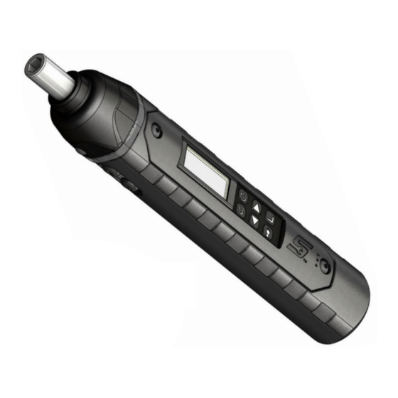
TORQUE-ANGLE
SCREWDRIVER
20-2109-SO REV. A
21-11
SAFETY INSTRUCTIONS
1
IMPORTANT SAFETY INSTRUCTIONS
35
IMPORTANTES INSTRUCTIONS DE SECURITE
36
INSTRUCCIONES DE SEGURIDAD IMPORTANTES
37
WICHTIGE SICHERHEITSHINWEISE
38
ISTRUZIONI CAUTELARI IMPORTANTI
39
BELANGRIJKE VEILIGHEIDSINSTRUCTIES
40
INSTRUÇÕES DE SEGURANÇA IMPORTANTES
®
Advertisement
Table of Contents

Related Manuals for Snap-On ControlTech


Summary of Contents for Snap-On ControlTech
- Page 1 ® ControlTech WIRELESS TORQUE-ANGLE SCREWDRIVER 20-2109-SO REV. A 21-11 SAFETY INSTRUCTIONS IMPORTANT SAFETY INSTRUCTIONS IMPORTANTES INSTRUCTIONS DE SECURITE INSTRUCCIONES DE SEGURIDAD IMPORTANTES WICHTIGE SICHERHEITSHINWEISE ISTRUZIONI CAUTELARI IMPORTANTI BELANGRIJKE VEILIGHEIDSINSTRUCTIES INSTRUÇÕES DE SEGURANÇA IMPORTANTES...
-
Page 2: Important Safety Instructions
Do not use on live electrical circuits. SAVE THESE INSTRUCTIONS Disclaimer Operation of ControlTech Wireless Screwdriver is not warranted in an EU member state if operating instructions are not in that State’s language. Contact Snap-on if a translation is needed. - Page 3 This equipment has been tested and found to comply with the limits for a Class B digital device, pursuant to Part 15 of the FCC rules. These limits are designed to provide reasonable protection against harmful interference in a residential installation. This equipment generates, uses, and can radiate radio frequency energy and, if not installed and used in accordance with the instructions, may cause harmful interference to radio communications.
-
Page 4: Specifications
Specifications Drive Type ¼” Hex Female ¼” Square Male Display DISPLAY TYPE: Dot Matrix LCD (168 x 48 Resolution) VIEWING ANGLE: 6:00 BACKLIGHT: WHITE (LED) Sealed Button Pad POWER - ON/OFF and torque and angle re-zero ENTER - measurement mode select and menu entry UP –... - Page 5 1. Turn On Screwdriver. While holding screwdriver still, momentarily press POWER button. Snap-on logo will be displayed followed by torque and angle re-zeroing screens (if angle mode has been previously selected). The target TORQUE or ANGLE screen will now be displayed depending on previous measurement mode selected.
- Page 6 2. Select Measurement Mode. Toggle between target TORQUE and ANGLE screens by repeatedly pressing ENTER button. Note: If screwdriver is powered up in torque only measurement mode, angle is not zeroed until keypad is unlocked and mode is changed to angle measurement mode. The Angle Zero Required screen will be displayed: ANGLE ZERO REQ Angle zeroing begins automatically after 2 seconds.
- Page 7 Mode Cycle Count 180° Mode cycle count feature is used to indicate number of times screwdriver has reached target torque in torque measurement mode or target angle in angle measurement mode. MEMORY ICON MODE CYCLE COUNT Torque and Angle Mode Cycle Counting 1.
-
Page 8: Clear Data
Note: Date and Time is blank if real-time-clock has not been set (see Setting Date and Time in the Advanced Configuration section. Deleting Stored Torque and Angle Data 1. From target torque or angle screen, press and hold ENTER button for 3 seconds. 2. - Page 9 ENTER EXIT button SHOW DATA held 80.00 IN-LB CLEAR DATA Target Screen UP/DOWN buttons Decimal Mark Selection menu Language Selection menu ENTER ENTER DECIMAL MARK CLEAR DATA ENGLISH button button COMMA (1,23) CYCLE COUNT FRANCAIS POINT (1.23) LANGUAGE ESPANOL UP/DOWN buttons DECIMAL MARK ENTER button COMMA (1,23)
- Page 10 5. MAXIMUM TORQUE screen is displayed next. MAXIMUM TORQUE is torque value above which red progress lights turn on. Initial MAXIMUM TORQUE value will be TARGET TORQUE value or MINIMUM TORQUE value (whichever is larger) plus 4%. Maximum torque value can be set greater than MINIMUM TORQUE value to 10% above screwdriver maximum range by pressing UP/DOWN buttons.
- Page 11 UNIT ADD PRESET button held 90° Target Angle Screen UP/DOWN buttons UP/DOWN buttons ENTER ADD PRESET MINIMUM ANGLE button ENTER button 90° ENTER button ENTER ENTER button BATCH COUNT MAXIMUM ANGLE PSET 02 button 94° 90° Preset Angle Screen UP/DOWN buttons UP/DOWN buttons Editing a Preset Edit PSET function gives user ability to edit stored PSETS on screwdriver.
- Page 12 Deleting a Preset Delete PSET function allows user to remove stored presets from screwdriver. 1. From Preset screen to be deleted, press and hold UNITS button for 3 seconds. 2. CHANGE PRESET screen is displayed. 3. Highlight DELETE menu selection using UP/DOWN buttons and press ENTER button. 4.
-
Page 13: Advanced Settings
Advanced Settings Accessing Advanced Settings Advanced settings are accessed from SETTINGS menu selection on main menu. 1. From target torque or angle screen, press and hold ENTER button for 3 seconds. 2. Highlight SETTINGS menu selection using UP/DOWN buttons. 3. -
Page 14: Sleep Time
SHOW INFO TCF: 4220 SLEEP TIME UP/DOWN buttons TFS+: 16155 TFS-: -16130 © 2018 SNAP-ON ENTER button Setting Sleep Time This function will allow user to set interval screwdriver enters power-down state following last applied torque or button press. 1. From Settings menu, use UP/DOWN buttons to highlight... - Page 15 EXIT SHOW INFO SLEEP TIME UP/DOWN buttons ENTER SHOW INFO button SLEEP TIME CONTRAST: 20 LCD CONTRAST UP/DOWN buttons CONTRAST: 80 ENTER button Key Beep Setup This function will allow user to enable or disable audio feedback when a button is pressed. 1.
-
Page 16: Auto Backlight
Auto Backlight Setup This function will allow user to enable or disable backlight from turning on during torque or angle measurement. 1. From Settings menu, use UP/DOWN buttons to highlight AUTO BACKLIGHT selection then press ENTER button. 2. AUTO BACKLIGHT screen is displayed. 3. - Page 17 Vibrator Configuration This function will allow user to configure vibrator for On or Off when target is reached for preference and/or battery power savings. 1. From Settings menu, use buttons to highlight VIBRATOR CONFIG selection then press ENTER button. 2. VIBRATOR CONFIG screen is displayed. 3.
-
Page 18: Pairing Mode
Pairing Mode Selection Screwdriver can be paired with a mobile device for increased security. Screwdriver supports two pairing modes: 1) NO PIN and 2) RANDOM PIN. In either mode, pairing screwdriver to a mobile device must be initiated from mobile device. If NO PIN mode is selected, neither screwdriver nor mobile device will ask for a PIN during pairing process. - Page 19 ENTER EXIT button SET HEAD LENGTH 80.0 held IN-LB SHOW DATA Target Screen UP/DOWN buttons Screwdriver not paired with mobile device PAIR STATE SETTINGS ENTER button UNPAIRED CONFIGURE EXIT PAIR STATE Screwdriver paired with mobile device PAIR STATE UNPAIR EXIT UP/DOWN buttons PAIR STATE UNPAIR...
-
Page 20: Advanced Configuration
Advanced Configuration Accessing Advanced Configuration Advanced configuration is accessed from CONFIGURE menu selection on main menu. Note: If screwdriver has been locked (see Preset Lock and Job Mode), a password entry is required to enter Configure menu. 1. From target torque or angle screen, press and hold ENTER button for 3 seconds. 2. - Page 21 Setting Target Tolerances This function will allow user to set plus and minus tolerances for torque and angle targets. Note: These tolerances are used for manual modes only. Preset tolerances are defined by Minimum and Maximum values. 1. From Mode Setup menu, use UP/DOWN buttons to highlight tolerance selection to setup (TQ-%, TQ+%, ANG-% ANG+%) then press ENTER button.
- Page 22 and if angle exceeds maximum angle, red progress lights turn on indicating a potential problem with fastener. 1. From target torque screen, use UP/DOWN buttons to set target torque and UNITS button to select torque measurement units then press ENTER button. 2.
-
Page 23: Preset Lock
Note: Password entry is required to enable Preset Lock. When locked, password entry is required to re-enter Configure menu (refer to ControlTech™ Wireless Screwdriver Calibration manual for default password). 1. From Configure menu, use UP/DOWN buttons to highlight... -
Page 24: Delete Preset
Note: REDO BATCH COUNT can only be enabled with PRESET LOCK enabled. Preset Unlock When Preset Lock is enabled, a password is required to access Configure menu. Refer to ControlTech™ Wireless Screwdriver Calibration Manual for Configure password. 1. From target torque or angle screen, press and hold ENTER button for 3 seconds. -
Page 25: Job Mode
This function locks all menus with password. Note: Password entry is required to enable Menu Lock. When locked, password entry is required to re-enter Main menu (refer to ControlTech™ Wireless Screwdriver Calibration manual for default password). 1. From Configure menu, use UP/DOWN buttons to highlight... -
Page 26: Set Date/Time
Change Password Change Password function allows user to change password to a new password. Default password is required to initially change password. Refer to ControlTech™ Wireless Screwdriver Calibration Manual for default password. 1. From Configure menu, use UP/DOWN buttons to highlight CHANGE PASSWD selection then press ENTER button. -
Page 27: Asset Tag
BLE Enable This function enables or disables the wireless radio. Note: Password entry is required to enable or disable the radio (refer to ControlTech™ Wireless Screwdriver Calibration manual for default password). 1. From Configure menu, use UP/DOWN buttons to highlight... - Page 28 Calibration Menu Selections: EXIT - Exits Calibration menu and returns to Configure menu. CAL TORQUE – Torque Calibration function (Refer to ControlTech™ Wireless Screwdriver Calibration manual). CAL ANGLE – Angle Calibration function (Refer to ControlTech™ Wireless Screwdriver Calibration manual).
- Page 29 Calibration Cycle Count Each time torque or angle target is reached, screwdriver calibration cycle counter is incremented. Maximum cycle count is 999999. 1. From Calibration Menu, highlight CAL CYCLE COUNT menu selection using UP/DOWN buttons. 2. Press ENTER button to display CAL CYCLE COUNT screen. 3.
- Page 30 Note: If warning count is set to zero and lock count is non-zero, CAL NEEDED screen is displayed when cal cycle count reaches lock count and no warning count displayed. Note: If warning count is set to non-zero and lock count is zero, CAL NEEDED screen is displayed when cal cycle count reaches warning count and no warning count displayed and screwdriver does not lock.
- Page 31 Setting Calibration Needed Countdown This function will allow user to set number of days when "CAL NEEDED" message will be displayed along with days remaining before a screwdriver lock out occurs due to calibration interval expiring. 1. From Calibration menu, use UP/DOWN buttons to highlight CAL COUNTDOWN selection then press ENTER button.
-
Page 32: Troubleshooting
Troubleshooting Note: If any of following issues persist, return screwdriver to an authorized Snap-on repair center. Issue Possible Cause Resolution Screwdriver does not turn on Dead/No batteries Replace batteries when POWER button Software glitch Cycle power using end-cap pressed. -
Page 33: Maintenance & Service
Clean screwdriver by wiping with a damp cloth. DO NOT use solvents, thinners or carburetor cleaners. DO NOT immerse in anything. Service and repairs are to be done by Snap-on Service Centers only. Contact your Snap-on Tools representative. NOTES: - If display shows persistent "TORQUE ZERO ERROR" at power on, screwdriver is damaged and must be returned for repair - If display shows “ANGLE ERROR”... -
Page 34: Battery Replacement
Battery Replacement Note: When replacing battery, real-time-clock will maintain date and time for 20 minutes. Note: Turn Battery End Cap clockwise to unscrew. Battery should be installed in carrier prior to carrier installation into screwdriver. Battery negative contact should be oriented towards carrier spring. 100% BATTERY UNSCREW END CAP LEVEL... - Page 35 OPTIONAL/AVAILABLE ACCESSORIES o MSTECHHDL Extension Handle o GMB3042 ¼” Hex to ¼” Ball Detent Square Adaptor (2 inch) o GMB3046 ¼” Hex to ¼” Ball Detent Square Adaptor (6 inch) o GMB3041 ¼” Hex Insert to Ball Detent Square Adaptor (1 inch) o TMC109A ¼”...
-
Page 36: Importantes Instructions De Securite
à l'intérieur d’un état membre de l'Union L'emploi de ce tournevis ControlTech Européenne si les instructions de fonctionnement ne sont pas dans la langue de l’état en question. Contacter Snap-on si vous avez besoin d’une traduction. Français... -
Page 37: Instrucciones De Seguridad Importantes
Descargo de responsabilidad El funcionamiento del destornillador no está garantizado en los países miembros de ControlTech la UE si las instrucciones de funcionamiento no figuran en el idioma del país en cuestión. Póngase en contacto con Snap-on si necesita una traducción. Español... -
Page 38: Wichtige Sicherheitshinweise
BEWAHREN SIE DIESE ANLEITUNG AUF Haftungsausschluss Es besteht keine Garantie für den Betrieb des Schraubendrehers in einem EU- ControlTech Mitgliedstaat, wenn die Betriebsanweisungen nicht in der betreffenden Landessprache abgefasst sind. Wenden Sie sich an Snap-on, wenn eine Übersetzung benötigt wird. Deutsch... -
Page 39: Esonero Di Responsabilità
Non utilizzare su circuiti elettrici sotto tensione. CONSERVARE QUESTE ISTRUZIONI ESONERO DI RESPONSABILITÀ: Non si garantisce l'uso della Cacciavite nei Paesi membri della CEE dove le ControlTech istruzioni per l'uso non sono in lingua locale. Contattare la Snap-on per l'eventuale traduzione. Italiano... -
Page 40: Belangrijke Veiligheidsinstructies
BEWAAR DEZE GEBRUIKSAANWIJZING Disclaimer Er geldt geen garantie voor het gebruik van de -schroevedraaier in lidstaten van ControlTech de EU als de gebruiksaanwijzing niet in de taal van het land in kwestie beschikbaar is. Neem contact op met Snap-on voor vertalingen. Nederlands... -
Page 41: Instruções De Segurança Importantes
A operação do chave de fenda não é permitida em nenhum Estado-membro da ControlTech União Europeia se as instruções operacionais não estiverem no idioma do Estado em questão. Entre em contato com a Snap-on se uma tradução for necessária. Português... - Page 44 Fax: 61-2-9837-9192 Carson City, NV 89706-0753 2068 Phone: 775-883-8585 Singapore Repair Center Fax: 775-883-8590 Korea Repair Center: Snap-on Tools Singapore Pte Ltd Snap-on Tools Korea 25 Tagore Lane, #01-01, CANADA #201-205, Sambo Techno Tower Singapore, 787602 Phone: 65-64515570 Western Repair Centre...
Need help?
Do you have a question about the ControlTech and is the answer not in the manual?
Questions and answers