Table of Contents
Advertisement
Quick Links
www.ti.com
EVM User's Guide: UCC217XXQDWEVM-054
UCC217xx and ISO5x5x Half-Bridge EVM User's Guide for
Wolfspeed 1200-V SiC Platforms
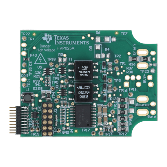
The UCC217XXQDWEVM-054 is a compact, half-bridge gate driver board consisting of two single-channel
isolated gate drivers. It provides isolated bias supply, drive current, protection and monitoring needed for driving
several different models of Wolfspeed silicon-carbide (SiC) MOSFET modules and other IGBT or SiC MOSFET
modules with a similar pinout. The on-board DC-DC transformers can provide adjustable isolated voltage.
The board's compact form factor, combined with UCC217xx's 5.7kVrms reinforced isolation, makes it a good
candidate for doing high voltage tests, such as double-pulse tests and short-circuit tests, with the Wolfspeed
SiC modules. The board can also be used with all variants of the UCC217xx and ISO5x5x family with minimal
on-board modifications.
This user's guide describes the characteristics, operation and use of the UCC217XX-054 Evaluation Module
(EVM). It also includes instructions to adjust different gate driver parameters, such as voltage supply and drive
strength, as well as instructions to modify the EVM to be compatible with different UCC217xx and ISO5x5x
variants. A complete schematic diagram, printed circuit board layouts, and bill of materials are included in this
document.
1 General TI High Voltage Evaluation User Safety Guidelines..............................................................................................
2.1 Supported Wolfspeed Modules and Evaluation Platforms.................................................................................................
2.2 Supported Gate Drivers.....................................................................................................................................................
3 System Overview and Functions..........................................................................................................................................
3.1 Features.............................................................................................................................................................................
3.2 Specifications.....................................................................................................................................................................
Pinout.........................................................................................................................................................................7
Diagram....................................................................................................................................................................7
EVM.......................................................................................................................................................................13
4.1 Equipment List.................................................................................................................................................................
4.2 Test Setups and Procedures............................................................................................................................................
5 EVM Example Measurements..............................................................................................................................................
Testing.........................................................................................................................................................16
5.2 Analog Sensing................................................................................................................................................................
6 EVM Tuning...........................................................................................................................................................................
6.1 Adjust Power Supplies.....................................................................................................................................................
6.2 Adjust Drive Strength.......................................................................................................................................................
6.3 Adaptations for Other ISO5x5x / UCC217xx Variants......................................................................................................
7 Hardware Design Files.........................................................................................................................................................
7.1
Schematics.......................................................................................................................................................................22
7.2 PCB Layouts....................................................................................................................................................................
7.3 Bill of Materials (BOM).....................................................................................................................................................
Information..........................................................................................................................................................33
8.1 Trademarks......................................................................................................................................................................
SLUUCK0 - SEPTEMBER 2023
Submit Document Feedback
ABSTRACT
Table of Contents
Compatibility..................................................................................................................................4
Copyright © 2023 Texas Instruments Incorporated
UCC217xx and ISO5x5x Half-Bridge EVM User's Guide for Wolfspeed 1200-V
Table of Contents
2
4
4
6
6
6
13
13
16
17
19
19
20
20
22
24
27
33
1
SiC Platforms
Advertisement
Table of Contents

Related Manuals for Texas Instruments UCC217 QDWEVM-054 Series


Summary of Contents for Texas Instruments UCC217 QDWEVM-054 Series
-
Page 1: Table Of Contents
7 Hardware Design Files................................. Schematics..................................22 7.2 PCB Layouts..................................7.3 Bill of Materials (BOM)..............................8 Additional Information................................33 8.1 Trademarks..................................SLUUCK0 – SEPTEMBER 2023 UCC217xx and ISO5x5x Half-Bridge EVM User's Guide for Wolfspeed 1200-V Submit Document Feedback SiC Platforms Copyright © 2023 Texas Instruments Incorporated... -
Page 2: General Ti High Voltage Evaluation User Safety Guidelines
– EVMs are not to be used as all or part of a production unit. UCC217xx and ISO5x5x Half-Bridge EVM User's Guide for Wolfspeed 1200-V SLUUCK0 – SEPTEMBER 2023 SiC Platforms Submit Document Feedback Copyright © 2023 Texas Instruments Incorporated... - Page 3 For safety, use of isolated test equipment with overvoltage and overcurrent protection is highly recommended. SLUUCK0 – SEPTEMBER 2023 UCC217xx and ISO5x5x Half-Bridge EVM User's Guide for Wolfspeed 1200-V Submit Document Feedback SiC Platforms Copyright © 2023 Texas Instruments Incorporated...
-
Page 4: Module And Gate Driver Compatibility
AIN/ASC • Miller clamp UCC21737-Q1 Supported External OC (0.7V) Optional Use circuit • AIN/ASC circuit UCC217xx and ISO5x5x Half-Bridge EVM User's Guide for Wolfspeed 1200-V SLUUCK0 – SEPTEMBER 2023 SiC Platforms Submit Document Feedback Copyright © 2023 Texas Instruments Incorporated... - Page 5 ISO5851 • Bypass AIN/ APWM ISO5851-Q1 APWM • Single output • Single output (optional) (optional) SLUUCK0 – SEPTEMBER 2023 UCC217xx and ISO5x5x Half-Bridge EVM User's Guide for Wolfspeed 1200-V Submit Document Feedback SiC Platforms Copyright © 2023 Texas Instruments Incorporated...
-
Page 6: System Overview And Functions
SHORT CIRCUIT PROTECTION - DESAT Ichg Blanking capacitor charging current Tdesatleb Leading edge blank time Tdesatfil DESAT deglitch filter UCC217xx and ISO5x5x Half-Bridge EVM User's Guide for Wolfspeed 1200-V SLUUCK0 – SEPTEMBER 2023 SiC Platforms Submit Document Feedback Copyright © 2023 Texas Instruments Incorporated... -
Page 7: Pcb Pinout
• Provides +12-V input to the board via the connector or the test point hooks. SLUUCK0 – SEPTEMBER 2023 UCC217xx and ISO5x5x Half-Bridge EVM User's Guide for Wolfspeed 1200-V Submit Document Feedback SiC Platforms Copyright © 2023 Texas Instruments Incorporated... - Page 8 The +12-V power supply and the PWM signals should be connected to the same board, either the differential board or the EVM. Failure to do so might result in EVM component damage. UCC217xx and ISO5x5x Half-Bridge EVM User's Guide for Wolfspeed 1200-V SLUUCK0 – SEPTEMBER 2023 SiC Platforms Submit Document Feedback Copyright © 2023 Texas Instruments Incorporated...
- Page 9 System Overview and Functions Figure 3-2. Primary-Side I/O SLUUCK0 – SEPTEMBER 2023 UCC217xx and ISO5x5x Half-Bridge EVM User's Guide for Wolfspeed 1200-V Submit Document Feedback SiC Platforms Copyright © 2023 Texas Instruments Incorporated...
- Page 10 SiC MOSFET/IGBT module. Test points are also placed near the output pins for easy measurement of the gate voltage. Figure 3-4. Output Stage Gate Loop UCC217xx and ISO5x5x Half-Bridge EVM User's Guide for Wolfspeed 1200-V SLUUCK0 – SEPTEMBER 2023 SiC Platforms Submit Document Feedback Copyright © 2023 Texas Instruments Incorporated...
- Page 11 UCC217xx calculator mentioned above is not accurate since it does not take into consideration of the additional charging current. Figure 3-5. DESAT Circuit SLUUCK0 – SEPTEMBER 2023 UCC217xx and ISO5x5x Half-Bridge EVM User's Guide for Wolfspeed 1200-V Submit Document Feedback SiC Platforms Copyright © 2023 Texas Instruments Incorporated...
- Page 12 If the AIN-APWM channel is not used, J4 can be left open or populated by a jumper. The APWM pin should be floated. Figure 3-7. Temperature-Sense System UCC217xx and ISO5x5x Half-Bridge EVM User's Guide for Wolfspeed 1200-V SLUUCK0 – SEPTEMBER 2023 SiC Platforms Submit Document Feedback Copyright © 2023 Texas Instruments Incorporated...
-
Page 13: Using The Evm
6. Make sure the 5-V green LED, the HS-BIAS blue LED, and the LS-BIAS blue LED are on. The two red RDY LEDs and the two red FLT LEDs should be off. SLUUCK0 – SEPTEMBER 2023 UCC217xx and ISO5x5x Half-Bridge EVM User's Guide for Wolfspeed 1200-V Submit Document Feedback SiC Platforms Copyright © 2023 Texas Instruments Incorporated... - Page 14 3. Measure the high-side gate voltage with the MMCX connector GATE1, and measure the low-side gate voltage with the MMCX connector GATE2. UCC217xx and ISO5x5x Half-Bridge EVM User's Guide for Wolfspeed 1200-V SLUUCK0 – SEPTEMBER 2023 SiC Platforms Submit Document Feedback Copyright © 2023 Texas Instruments Incorporated...
- Page 15 21.6% with ±3% accuracy. Figure 4-3. Test Point Locations for AIN-APWM Check SLUUCK0 – SEPTEMBER 2023 UCC217xx and ISO5x5x Half-Bridge EVM User's Guide for Wolfspeed 1200-V Submit Document Feedback SiC Platforms Copyright © 2023 Texas Instruments Incorporated...
-
Page 16: Evm Example Measurements
As the figure shows, when the SiC MOSFET undergoes soft turn-off, the Vds overshoot is greatly reduced to approximately 170 V. UCC217xx and ISO5x5x Half-Bridge EVM User's Guide for Wolfspeed 1200-V SLUUCK0 – SEPTEMBER 2023 SiC Platforms Submit Document Feedback Copyright © 2023 Texas Instruments Incorporated... -
Page 17: Analog Sensing
The table below shows a test carried out by connecting resistors of different values onto the J4 headers. The AIN voltage, APWM duty cycle, and duty cycle error are included in the table. SLUUCK0 – SEPTEMBER 2023 UCC217xx and ISO5x5x Half-Bridge EVM User's Guide for Wolfspeed 1200-V Submit Document Feedback SiC Platforms Copyright © 2023 Texas Instruments Incorporated... - Page 18 13.58% 13.6% -0.02% 4.45V 10.83% 11.0% -0.17% 4.51V 9.59% 9.8% -0.21% 4.73V 5.17% 5.4% -0.23% UCC217xx and ISO5x5x Half-Bridge EVM User's Guide for Wolfspeed 1200-V SLUUCK0 – SEPTEMBER 2023 SiC Platforms Submit Document Feedback Copyright © 2023 Texas Instruments Incorporated...
-
Page 19: Evm Tuning
× R = − 1 + × 2.5V + 30nA × R R 35 R 35 SLUUCK0 – SEPTEMBER 2023 UCC217xx and ISO5x5x Half-Bridge EVM User's Guide for Wolfspeed 1200-V Submit Document Feedback SiC Platforms Copyright © 2023 Texas Instruments Incorporated... -
Page 20: Adjust Drive Strength
Miller clamp; an external Miller clamp can be used. • Q3 and Q6 FETs UCC217xx and ISO5x5x Half-Bridge EVM User's Guide for Wolfspeed 1200-V SLUUCK0 – SEPTEMBER 2023 SiC Platforms Submit Document Feedback Copyright © 2023 Texas Instruments Incorporated... - Page 21 Populate R38 and R73 with 0-Ω resistors connected to GND. • R38 and R73 or jumpers SLUUCK0 – SEPTEMBER 2023 UCC217xx and ISO5x5x Half-Bridge EVM User's Guide for Wolfspeed 1200-V Submit Document Feedback SiC Platforms Copyright © 2023 Texas Instruments Incorporated...
-
Page 22: Hardware Design Files
Misc 5125 5127 VEE_HS Testpoints GND3 SC_HS SC_LS 5016 COM_LS Figure 7-1. UCC21710 EVM Schematic UCC217xx and ISO5x5x Half-Bridge EVM User's Guide for Wolfspeed 1200-V SLUUCK0 – SEPTEMBER 2023 SiC Platforms Submit Document Feedback Copyright © 2023 Texas Instruments Incorporated... - Page 23 Misc 5125 5127 VEE_HS Testpoints GND3 SC_HS SC_LS 5016 COM_LS Figure 7-2. UCC21750 EVM Schematic SLUUCK0 – SEPTEMBER 2023 UCC217xx and ISO5x5x Half-Bridge EVM User's Guide for Wolfspeed 1200-V Submit Document Feedback SiC Platforms Copyright © 2023 Texas Instruments Incorporated...
-
Page 24: Pcb Layouts
Hardware Design Files www.ti.com 7.2 PCB Layouts Figure 7-3. Top Layer UCC217xx and ISO5x5x Half-Bridge EVM User's Guide for Wolfspeed 1200-V SLUUCK0 – SEPTEMBER 2023 SiC Platforms Submit Document Feedback Copyright © 2023 Texas Instruments Incorporated... - Page 25 Hardware Design Files Figure 7-4. Signal Layer 1 SLUUCK0 – SEPTEMBER 2023 UCC217xx and ISO5x5x Half-Bridge EVM User's Guide for Wolfspeed 1200-V Submit Document Feedback SiC Platforms Copyright © 2023 Texas Instruments Incorporated...
- Page 26 Hardware Design Files www.ti.com Figure 7-5. Signal Layer 2 UCC217xx and ISO5x5x Half-Bridge EVM User's Guide for Wolfspeed 1200-V SLUUCK0 – SEPTEMBER 2023 SiC Platforms Submit Document Feedback Copyright © 2023 Texas Instruments Incorporated...
-
Page 27: Bill Of Materials (Bom)
0402 (1005 Metric) 0.01uF CAP, CERM, 0.01 uF, 50 V, +/- 10%, X7R, C0603X103K5RACTU 0603 SLUUCK0 – SEPTEMBER 2023 UCC217xx and ISO5x5x Half-Bridge EVM User's Guide for Wolfspeed 1200-V Submit Document Feedback SiC Platforms Copyright © 2023 Texas Instruments Incorporated... - Page 28 R15, R36, R39, R60, R74, RES, 0, 5%, 0.125 W, 0603 MCT06030Z0000ZP500 R92, R102, R106 UCC217xx and ISO5x5x Half-Bridge EVM User's Guide for Wolfspeed 1200-V SLUUCK0 – SEPTEMBER 2023 SiC Platforms Submit Document Feedback Copyright © 2023 Texas Instruments Incorporated...
- Page 29 0.027uF CAP, CERM, 0.027 uF, 50 V, +/- 10%, X7R, 06035C273K4T2A AEC-Q200 Grade 1, 0603 SLUUCK0 – SEPTEMBER 2023 UCC217xx and ISO5x5x Half-Bridge EVM User's Guide for Wolfspeed 1200-V Submit Document Feedback SiC Platforms Copyright © 2023 Texas Instruments Incorporated...
- Page 30 CAP, CERM, 1 µF, 25 V,+/- 10%, X7R, AEC- CGA3E1X7R1E105K080AC Q200 Grade 1, 0603 COM3, COM4, GND1, Testpoint TP_H0.45P0.75 GND2 UCC217xx and ISO5x5x Half-Bridge EVM User's Guide for Wolfspeed 1200-V SLUUCK0 – SEPTEMBER 2023 SiC Platforms Submit Document Feedback Copyright © 2023 Texas Instruments Incorporated...
- Page 31 RES, 2.32 M, 1%, 0.063 W, AEC-Q200 CRCW04022M32FKED Grade 0, 0402 208k RES, 208 k, 0.5%, 0.1 W, 0603 RT0603DRE07208KL SLUUCK0 – SEPTEMBER 2023 UCC217xx and ISO5x5x Half-Bridge EVM User's Guide for Wolfspeed 1200-V Submit Document Feedback SiC Platforms Copyright © 2023 Texas Instruments Incorporated...
- Page 32 AEC-Q200 Grade 1, 0603 FID4, FID5, FID6 Fiducial mark. There is nothing to buy or mount. UCC217xx and ISO5x5x Half-Bridge EVM User's Guide for Wolfspeed 1200-V SLUUCK0 – SEPTEMBER 2023 SiC Platforms Submit Document Feedback Copyright © 2023 Texas Instruments Incorporated...
-
Page 33: Additional Information
(SOT-23-3) 8 Additional Information 8.1 Trademarks All trademarks are the property of their respective owners. SLUUCK0 – SEPTEMBER 2023 UCC217xx and ISO5x5x Half-Bridge EVM User's Guide for Wolfspeed 1200-V Submit Document Feedback SiC Platforms Copyright © 2023 Texas Instruments Incorporated... - Page 34 STANDARD TERMS FOR EVALUATION MODULES Delivery: TI delivers TI evaluation boards, kits, or modules, including any accompanying demonstration software, components, and/or documentation which may be provided together or separately (collectively, an “EVM” or “EVMs”) to the User (“User”) in accordance with the terms set forth herein.
- Page 35 www.ti.com Regulatory Notices: 3.1 United States 3.1.1 Notice applicable to EVMs not FCC-Approved: FCC NOTICE: This kit is designed to allow product developers to evaluate electronic components, circuitry, or software associated with the kit to determine whether to incorporate such items in a finished product and software developers to write software applications for use with the end product.
- Page 36 www.ti.com Concernant les EVMs avec antennes détachables Conformément à la réglementation d'Industrie Canada, le présent émetteur radio peut fonctionner avec une antenne d'un type et d'un gain maximal (ou inférieur) approuvé pour l'émetteur par Industrie Canada. Dans le but de réduire les risques de brouillage radioélectrique à...
- Page 37 www.ti.com EVM Use Restrictions and Warnings: 4.1 EVMS ARE NOT FOR USE IN FUNCTIONAL SAFETY AND/OR SAFETY CRITICAL EVALUATIONS, INCLUDING BUT NOT LIMITED TO EVALUATIONS OF LIFE SUPPORT APPLICATIONS. 4.2 User must read and apply the user guide and other available documentation provided by TI regarding the EVM prior to handling or using the EVM, including without limitation any warning or restriction notices.
- Page 38 Notwithstanding the foregoing, any judgment may be enforced in any United States or foreign court, and TI may seek injunctive relief in any United States or foreign court. Mailing Address: Texas Instruments, Post Office Box 655303, Dallas, Texas 75265 Copyright © 2023, Texas Instruments Incorporated...
- Page 39 TI products. TI’s provision of these resources does not expand or otherwise alter TI’s applicable warranties or warranty disclaimers for TI products. TI objects to and rejects any additional or different terms you may have proposed. IMPORTANT NOTICE Mailing Address: Texas Instruments, Post Office Box 655303, Dallas, Texas 75265 Copyright © 2023, Texas Instruments Incorporated...
Need help?
Do you have a question about the UCC217 QDWEVM-054 Series and is the answer not in the manual?
Questions and answers