Advertisement
Quick Links
WARNING AND CAUTIONS:
TO AVOID FIRE, SHOCK, OR DEATH: TURN OFF POWER AT CIRCUIT BREAKER
OR FUSE AND TEST THAT POWER IS OFF BEFORE INSTALLING!
PROPER GROUNDING REQUIRED TO AVOID STATIC DISCHARGE WHICH
CAN DAMAGE CONTROLLERS DURING INSTALLATION.
SPECIFICATIONS
Dim Control Max Load: 10 mA Source/Sink
Radio Frequency: 2.4 GHz (IEEE 802.15.4)
RF Transmission Output Power: +20 dBm
Operating Temperature: -40 to +80 C
Operating Humidity: 10 to 90%, non-condensing
Wire Size: 18 AWG, 8" Wires, UL1316, 600V
Dimensions: 2.25" L x 2.0" W x .3" H
(57 x 50.8 x 7.6 mm)
DESIGN CONSIDERATIONS
Below are some recommendations for successful
dimming using the DIM10-087-06-F3W. The dimming
control wires are referenced as DIM+ and DIM-. The
dimming signals have a Maximum voltage of 10V DC.
Do not ground the DIM- wire to chassis ground;
this is a return signal and is critical for proper
dimming.
Route dimming wires away from AC lines if
possible.
Maximum 0f 8 DIM to OFF LED Drivers.
Do not mount to a heatsink or to a LED driver.
When installing the DIM10-087-06-F3W into an
enclosure, consideration of the internal antenna
position and any possible interference is required
to provide the best wireless signal strength. Prior
to permanently mounting it, make sure the device
is free of any metal objects within 2 inches.
NOTE: LED Driver must support DIM to OFF functionality.
DIM10-087-06-F3W Controller
Load Ratings: 12 to 24VDC, +/-10%, 900mW max
Operating Humidity: 10 to 90%, non-condensing
WARNING AND CAUTIONS:
INSTALLATION GUIDE
NEEDED MATERIAL
Mounting Hardware: (1) #4 or M3 screws and
standoff recommended
INSTALLATION INSTRUCTIONS
MOUNTING
1.
Place the controller in desired location and secure
it using #4 sized screw and standoff using the
mounting hole located in the center of the board.
Note: For the best RF signal propagation, mount
the controller so that the bottom is facing the
ground.
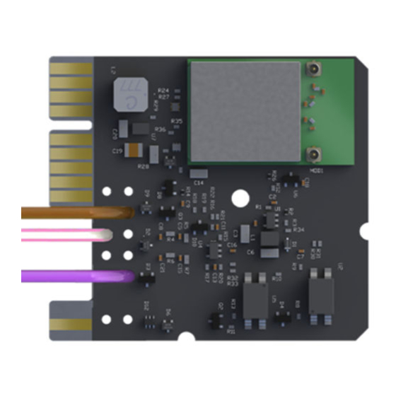
WIRING THE DIM10-087-06-F3W
CONTROLLER
2.
Connect the POWER (BROWN) wire of the DIM10-
087-06-F3W to the 12-24V DC Aux output from
the LED driver.
3.
Connect the DIM+ (PURPLE) wire from the DIM10-
087-06-F3W to the DIM+ wire on the LED driver.
4.
Connect the DIM- (PINK/WHITE STRIPE) wire from
the DIM10-087-06-F3W to the COMMON/DIM- wire
on the LED driver.
(See Figure 1 on page 2)
If you are unsure about any part of these instructions, consult an electrician; all
work should be performed by qualified personnel.
DIM10-087-06-F3W controllers must be installed in accordance with national, state,
and local electrical codes and requirements.
POWERING UP THE FIXTURE AND
CONTROLLER
After connecting the Controller to the LED Driver,
switch power on to the fixture. The light should turn
on.
STATUS LED
Note: When the controller is powered, the
following colors indicate the status.
Red = No Network Found (Communication Lost)
Blinking Green = Network Found, Controller Not
Configured (Device not yet added to SimplySnap)
Green = Network Found, Controller Configured
(Normal Operation)
For more information on SimplySnap and the DIM10-
087-06-F3W, refer to the website at
http://help.synapsewireless.com/.
21-D08706F3W-INS A-5
Advertisement

Related Manuals for Synapse DIM10-087-06-F3W


Summary of Contents for Synapse DIM10-087-06-F3W
- Page 1 PROPER GROUNDING REQUIRED TO AVOID STATIC DISCHARGE WHICH DIM10-087-06-F3W controllers must be installed in accordance with national, state, CAN DAMAGE CONTROLLERS DURING INSTALLATION. and local electrical codes and requirements. INSTALLATION GUIDE...
- Page 2 Figure 1 - DIM to OFF Wiring Diagram WARNING: · If a single Synapse controller is used to drive the DIM+ input of multiple LED drivers, then all of the DIM- lines from all drivers MUST be directly tied/shorted together to provide a common return/ground to the controller.
Need help?
Do you have a question about the DIM10-087-06-F3W and is the answer not in the manual?
Questions and answers