Advertisement
Quick Links
WARNING AND CAUTIONS:
•
TO AVOID FIRE, SHOCK, OR DEATH; TURN OFF POWER AT CIRCUIT
BREAKER OR FUSE AND TEST THAT POWER IS OFF BEFORE WIRING!
•
To be installed and/or used in accordance with appropriate electrical codes
and regulations.
•
If you are unsure about any part of these instructions, consult an electrician.
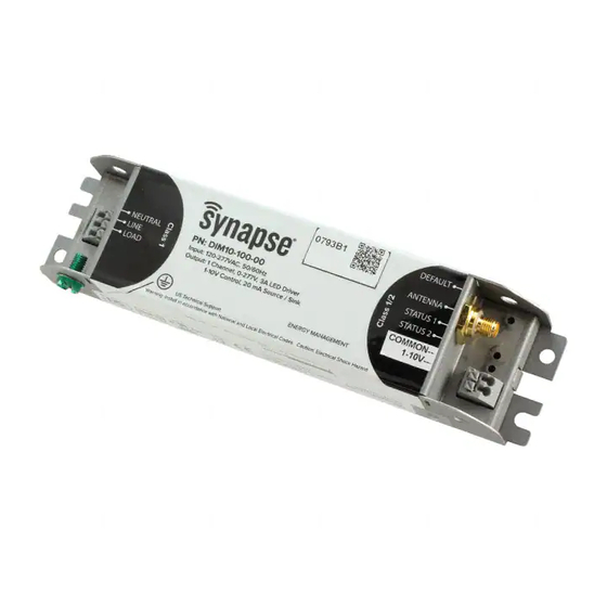
ORDERING INFORMATION
Part Number: DIM10-100-00
FEATURES
•
True ON/OFF switching via relay, up to 2A load
•
0-10V dimming, up to 10mA source/sink
•
Pushbutton terminal blocks for easy installation
RATINGS
Voltage Input: 100-277 VAC (+/-10%), 50/60 Hz
Voltage Output (Max): 305V
Power Consumption (No Load): 0.3W @ 277VAC;
0.5W @ 120VAC
DESCRIPTION
The Synapse DIM10-100-00 controls LED lighting in
commercial and industrial buildings using the SNAP
wireless mesh network. It uses an internal relay
to provide True On/Off capability, and it provides
0-10V analog dimming control using a true On/Off
0-10V standard dimming protocol. Synapse lighting
controllers can be controlled with a browser-based
application available with the Synapse SimplySNAP
lighting solution.
SPECIFICATIONS
Relay Max Switched Circuit: Zero Cross, 2A
Dim Control Max Load: 10 mA Source/Sink
Radio Frequency: 2.4 GHz (IEEE 802.15.4)
RF Transmission Output Power: +20dBM
Operating Temperature: -20 to +60 C
Operating Humidity: 10 to 90%, non-condensing
Dimensions: 7.1"L x 1.8"W X 1"H (181 X 46 X 26 mm)
Enclosure Type: Galvanneal steel
Configuration/Programming: Stored in non-volatile
memory
INSTALLATION
DIM10-100-00
Load Ratings: 2A @ 100-277VAC (+/- 10%)
Installation Guide
•
Disconnect power at circuit breaker or fuse when servicing, installing or
removing fixture or changing lamps.
•
Risk of Electric Shock - More than one disconnect switch may be required to
de-energize the equipment before servicing. Use this device with copper or
copper clad wire only.
CAUTION
•
DIM10-100-00 controllers must be installed
in accordance with national, state, and local
electrical codes and requirements
•
All work must be performed by qualified
personnel
•
Disconnect all power before installation or
service
•
Metal conduit connector must be grounded
•
The switched output (LOAD) is energized by
default at power up
Needed Materials
Wiring Connectors: All existing wiring connectors
must be replaced with new UL listed wiring
connectors. All wiring connectors must be correctly
sized for the application and the number and the
size of the electrical conductors.
Mounting: Secure with four #8 screws. See the
DIM10-100-00 mounting template for assistance.
Mounting Options: Mount in an LED Fixture or
a Troffer. See figure 1 below for proper antenna
orientation.
Installation Instructions
1.
WARNING: TO AVOID FIRE, SHOCK, OR
DEATH: TURN OFF POWER AT CIRCUIT
BREAKER OR FUSE AND VERIFY THAT
POWER IS OFF BEFORE WIRING!
2. Place DIM10-100-00 in desired location and
secure it using #8 screws or other appropriate
methods. Prior to permanently mounting the
DIM10-100-00, make sure the antenna points
directly upward or downward and is free of
any metal objects within 12 in. of the antenna.
(Figure 1)
WARNINGS AND CAUTIONS:
Note: When installing the DIM10-100-00 into an
enclosure, consideration of antenna position and
interference is required in order to provide the most
optimum wireless signal strength.
DON'T
This Way Up
FIGURE 1 - ANTENNA ORIENTATION
3. Disconnect the hot wire (black) from the LED
fixture and connect it to the LINE input on the
DIM10-100-00.
4. Connect the black wire of the LED fixture to the
LOAD output on the DIM10-100-00.
5. Connect the white wire (neutral) of the LED
DO
116-081509-004-A003
Advertisement

Related Manuals for Synapse DIM10-100-00


Summary of Contents for Synapse DIM10-100-00
- Page 1 If you are unsure about any part of these instructions, consult an electrician. copper clad wire only. CAUTION ORDERING INFORMATION Part Number: DIM10-100-00 Note: When installing the DIM10-100-00 into an • DIM10-100-00 controllers must be installed enclosure, consideration of antenna position and in accordance with national, state, and local...
- Page 2 FCC ID. Modifications (FCC 15.21): Changes or modifications to this equipment not expressly Blue LOAD RF Exposure Statement: This equipment complies with approved by Synapse Wireless, Inc., may void the user’s authority ANTENNA Black LINE Dim-...
Need help?
Do you have a question about the DIM10-100-00 and is the answer not in the manual?
Questions and answers