Table of Contents
Advertisement
Quick Links
WARNING AND CAUTIONS:
•
TO AVOID FIRE, SHOCK, OR DEATH: TURN OFF POWER AT CIRCUIT BREAKER
OR FUSE AND TEST THAT POWER IS OFF BEFORE INSTALLING!
•
PROPER GROUNDING REQUIRED TO AVOID STATIC DISCHARGE WHICH
CAN DAMAGE CONTROLLERS DURING INSTALLATION.
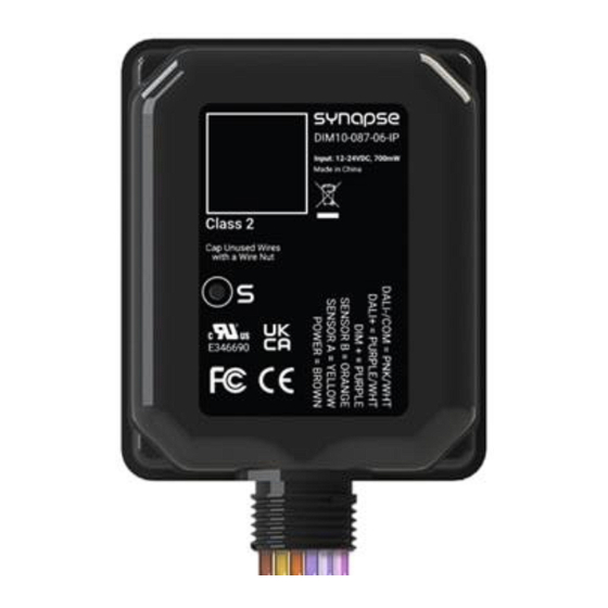
SPECIFICATIONS
•
Dim Control Max Load: 10 mA Source/Sink
•
Radio Frequency: 2.4 GHz (IEEE 802.15.4)
•
RF Transmission Output Power: +20 dBm
•
Operating Temperature: -40°C to +80°C
•
Operating Humidity: 10 to 90%, non-condensing
•
Max D4i Drivers: Limited to 4 D4i LED drivers
•
IP Rating: IP66
•
Wire Size: 18 AWG, 7" Wires, UL1316, 600V
•
Dimensions: 3.7" L x 2.8" W x 0.9" H
(94 x 71 x 23 mm)
DESIGN CONSIDERATIONS
Below are some recommendations for successful dimming
using the DIM10-087-06-IP. The dimming control wires
are referenced as DIM+ and DALI-/COM. The dimming
signals have a Maximum voltage of 10V DC.
•
Do not ground the DALI-/COM wire to chassis
ground; this is a return signal and is critical for
proper dimming.
•
Route dimming wires away from AC lines if
possible.
•
Maximum of 4 DALI-2/D4i LED Drivers per
controller, consult Synapse Support if a greater
ratio is needed.
•
Maximum 0f 8 DIM to OFF LED Drivers for DIM to
OFF Designs.
•
Do not mount to a heatsink or to an LED driver.
•
When installing the DIM10-087-06-IP into a light
fixture, consideration of the internal antenna
position and any interference is required to provide
the best wireless signal strength. Prior to
permanently mounting it, make sure the device is
free of any metal objects within 2 inches.
NOTE: LED Driver must support DIM to OFF functionality.
DIM10-087-06-IP Controller
Load Ratings: 12 to 24VDC, +/-10%, 900mW max
Operating Humidity: 10 to 90%, non-condensing
WARNING AND CAUTIONS:
•
•
•
INSTALLATION GUIDE
WARNING: The maximum number of D4i LED Drivers
with active DALI power supply on the bus is 4. Up to 6
D4i LED drivers may be on the bus, but only 4 may
have active power supplies. SimplySnap will not
support more than 6 D4i LED drivers on the Synapse
lighting controller. The DALI bus is limited to 250mA.
Having more than 4 DALI power supplies on the bus
may void the D4i LED driver warranty.
INSTALLATION INSTRUCTIONS
MOUNTING
1.
Remove the locking nut from the DIM10-087-06-
IP.
2.
Insert the DIM10-087-06-IP into the knockout of
the light fixture.
3.
Re-attach the locking nut on the DIM10-087-06-IP
threads from inside the light fixture.
Note: For the best RF signal propagation, mount
the DIM10-087-06-IP so that the bottom is facing
the ground.
WIRING THE DIM10-087-06-IP
CONTROLLER
Note: Unless specified, the connections to a
standard Dim to Off LED driver and the DALI 2
LED driver are the same.
4.
Connect the POWER (BROWN) wire of the DIM10-
087-06-IP to the 12-24V DC Aux output from the
LED driver, rated max 15W.
5.
Connect the DALI-/COMMON (PINK/WHITE
STRIPE) to the COMMON wire on the LED driver
you have.
If you are unsure about any part of these instructions, consult an electrician; all
work should be performed by qualified personnel.
DIM10-087-06-IP controllers must be installed in accordance with national, state,
and local electrical codes and requirements.
CONNECTING SENSORS
Note: Steps 6-10 are for adding sensors to the
DIM10-087-06-IP controller; if you are not
connecting sensors skip this section.
There are two sensor inputs on the DIM10-087-06-IP
designed for low powered (24V DC) type sensors.
•
The
connect sensor A.
•
The
connect sensor B.
6.
Connect the sensor power wire to the AUX out on
the LED driver (the LED driver powers the sensor).
7.
Connect the sensor common to the
COMMON/DIM-.
8.
Connect the
SENSOR B (ORANGE) wire
controller to the sensor CTRL/Control wire.
9.
If you are using more than one sensor, then
duplicate the installation as described above.
10.
Sensors must be configured in software before
they are functional in a SimplySnap system.
(See Figures 1 and 2)
CONNECTING THE DIMMING CIRCUIT
Note: Steps 11-12 are for connecting to a
Standard Dim to Off LED driver; if you are using a
DALI 2 LED driver skip to steps 13-14.
11.
Connect the DIM+ (PURPLE) wire from the DIM10-
087-06-IP to the DIM+ wire on the LED driver.
12.
Cap the unused DALI+ (PURPLE/WHITE STRIPE)
wire.
(See Figure 1)
SENSOR A (YELLOW)
wire is used to
SENSOR B (ORANGE)
wire is used to
SENSOR A (YELLOW) wire or the
of the DIM10-087-06-IP
21-D08706IP-INS A-0
Advertisement
Table of Contents

Related Manuals for Synapse DIM10-087-06-IP


Summary of Contents for Synapse DIM10-087-06-IP
- Page 1 • PROPER GROUNDING REQUIRED TO AVOID STATIC DISCHARGE WHICH • DIM10-087-06-IP controllers must be installed in accordance with national, state, CAN DAMAGE CONTROLLERS DURING INSTALLATION. and local electrical codes and requirements. • INSTALLATION GUIDE...
- Page 2 Switch power on to the fixture. The light should turn WARNING: · If a single Synapse controller is used to drive the DIM+ input of multiple LED drivers, then all of the DIM- lines from all drivers STATUS LED MUST be directly tied/shorted together to provide a common return/ground to the controller.
- Page 3 REGULATORY INFORMATION AND Declaration of Conformity (FCC 96-208 & 95-19): CERTIFICATIONS Synapse Wireless, Inc. declares that the product name “DIM10-087-06-IP” to which this declaration relates, RF Exposure Statement: This equipment complies meet the requirements specified by the Federal with FCC radiation exposure limits set forth for an Communications Commission as detailed in the uncontrolled environment.
Need help?
Do you have a question about the DIM10-087-06-IP and is the answer not in the manual?
Questions and answers