Advertisement
WARNING AND CAUTIONS:
•
TO AVOID FIRE, SHOCK, OR DEATH; TURN OFF POWER AT CIRCUIT BREAKER
OR FUSE AND TEST THAT POWER IS OFF BEFORE INSTALLING!
SPECIFICATIONS
•
Dim Control Max Load: 10 mA Source/Sink
•
Radio Frequency: 2.4 GHz (IEEE 802.15.4)
•
RF Transmission Output Power: +15dBM
•
Operating Temperature: -40 to +85 C
•
Operating Humidity: 10 to 90%, non-condensing
•
Dimensions: 2"L x 1.6"W X .3"H
(51 X 40.7 X 6.4 mm)
•
Configuration/Programming: Stored in non-volatile
memory
CAUTION
•
DIM10-087-00 Series controllers must be installed
in accordance with national, state, and local
electrical codes and requirements
NEEDED MATERIALS
•
u.FL Insertion Tool: Part Number U.FL-LP-IN
from Hirose Electric (for DIM10-087-00 only)
•
u.FL Extraction Tool: Part Number U.FL-LP-N-2
from Hirose Electric (for DIM10-087-00 only)
•
u.FL Connector and 14mm bulkhead: A cable
with a u.FL connector on one end and a female
14mm bulkhead connector on the other end is
required to route the signal from the DIM10-087-
00 through the fixture housing to an external
antenna. Synapse has kits available for these
cables as part numbers:
KIT-ANTUFL18-01
KIT-ANTUFL18-02
KIT-ANTUFL18-03
KIT-ANTUFL18-04
Contact Synapse for further information.
•
50 OHM Terminator plug RP-SMA: Part Number
132360RP from Amphenol.
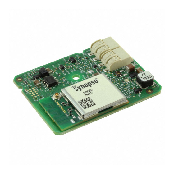
DIM10-087-00 Lighting Controller
Load Ratings: 1.2W @ 5 to 24V DC
Operating Temperature: -40 to +85 C / Operating Humidity: 10 to 90%, non-condensing
INSTALLATION GUIDE
•
Wiring Connectors: All existing wiring connectors
must be replaced with new UL listed wiring
connectors. All wiring connectors must be correctly
sized for the application and the number and the
size of the electrical conductors.
•
Mounting: Secure with 1 #4 screw (max
diameter of .312 inches) and standoff.
•
Mounting Options: Mount in an LED Fixture or a
Troffer. For the DIM10-087-00, an external
antenna utilizing a u.FL connector must be used to
provide RF connectivity to the SNAP mesh
network.
INSTALLATION INSTRUCTIONS
WARNING: TO AVOID FIRE, SHOCK, OR
DEATH: TURN OFF POWER AT CIRCUIT
BREAKER OR FUSE AND VERIFY THAT POWER IS
OFF BEFORE WIRING!
1.
Place the DIM10-087-00 in desired location and
secure it using #4 sized screw and stand-off using
the mounting hole located in the center of the
board. Prior to permanently mounting the DIM10-
087-00, make sure the antenna is free of any
objects within 3 in. of the internal or external
antenna.
Figure 1 - Wiring Diagram
WARNING AND CAUTIONS:
•
If you are unsure about any part of these instructions, consult an electrician; all
work should be performed by qualified personnel
•
Disconnect power at circuit breaker or fuse when servicing, installing or removing
fixture or changing lamps.
Note: When installing the DIM10-087-00 into an
enclosure, consideration of the internal or external
antenna position and interference is required in order
to provide the most optimum wireless signal strength.
2.
Connect the 5-24VDC Aux output from LED
driver to terminal block pin J4.1 on the
DIM10-087-00. (See Figure 2 to better
identify terminal block pins.)
3.
Connect the Aux ground from the LED driver
to terminal block pin J4.2 on the DIM10-087-
00.
Figure 2- Terminal Block PINS
Note: Steps 4-7 are for Class 1/2 Dimming
Control
4.
Connect the DIM- wire on the LED driver to
the DIM- input on terminal block pin J5.2 on
the DIM10-087-00.
5.
Connect the DIM+ wire on the LED driver to
the DIM+ input on terminal block pin J5.1 on
the DIM10-087-00.
116-081509-003-C-0
Advertisement
Table of Contents

Related Manuals for Synapse DIM10-087-00


Summary of Contents for Synapse DIM10-087-00
- Page 1 INSTALLATION GUIDE SPECIFICATIONS • Wiring Connectors: All existing wiring connectors Note: When installing the DIM10-087-00 into an • Dim Control Max Load: 10 mA Source/Sink must be replaced with new UL listed wiring enclosure, consideration of the internal or external •...
- Page 2 • Number of fixtures that can be daisy-chained strap. After installing the bulkhead in the fixture, Please see the DIM10-087-00 Series cut sheet or is dependent upon the following factors: contact Synapse sales for more information. replace the 50 OHM Terminator.
- Page 3 20cm Declaration of Conformity (FCC 96-208 & 95-19): between the radiator and your body. This transmitter Synapse Wireless, Inc. declares that the product name must not be co-located or operating in conjunction with “DIM10-087-00” and “DIM10-087-00-F” to which this any other antenna or transmitter.
Need help?
Do you have a question about the DIM10-087-00 and is the answer not in the manual?
Questions and answers