Table of Contents
Advertisement
Quick Links
Warning AND CAUTIONS:
•
TO AVOID FIRE, SHOCK, OR DEATH: TURN OFF POWER AT CIRCUIT BREAKER
OR FUSE AND TEST THAT POWER IS OFF BEFORE INSTALLING!
•
PROPER GROUNDING REQUIRED TO AVOID STATIC DISCHARGE WHICH
CAN DAMAGE CONTROLLERS DURING INSTALLATION.
SPECIFICATIONS
•
Dim Control Max Load: 10 mA Source/Sink
•
Radio Frequency: 2.4 GHz (IEEE 802.15.4)
•
RF Transmission Output Power: +20 dBm
•
Operating Temperature: -40°C to +80°C
•
Operating Humidity: 10 to 90%, non-condensing
•
Max D4i Drivers: Limited to 4 D4i LED drivers
•
Wire Size: 20 AWG, 7" Wires, 600V
•
Dimensions: 3.05" L x 2.21" W x .47" H
(77.6 x 56.1 x 11.8 mm)
CAUTION
DIM10-087-06-A controllers must be installed in
accordance with national, state, and local electrical
codes and requirements.
DESIGN CONSIDERATIONS
Below are some recommendations for successful dimming
using the DIM10-087-06-A. The dimming control wires
are referenced as DIM+ and DALI-/COM. The dimming
signals have a Maximum voltage of 10V DC.
•
Do not ground the DALI-/COM wire to chassis
ground; this is a return signal and is critical for
proper dimming.
•
Route dimming wires away from AC lines if
possible.
•
Maximum of 4 DALI-2/D4i LED Drivers per
controller for DALI-2/D4i Designs.
•
Maximum 0f 8 DIM to OFF LED Drivers for DIM to
OFF Designs.
•
Do not mount to a heatsink or to an LED driver.
•
When installing the DIM10-087-06-A into an
enclosure, consideration of the external antenna
position and interference is required to provide the
most optimum wireless signal strength. Prior to
permanently mounting it, make sure the antenna
points directly upward or downward and is free of
any metal objects within 2 in. of the antenna
(Figure 1).
NOTE: LED Driver must support DIM to OFF functionality.
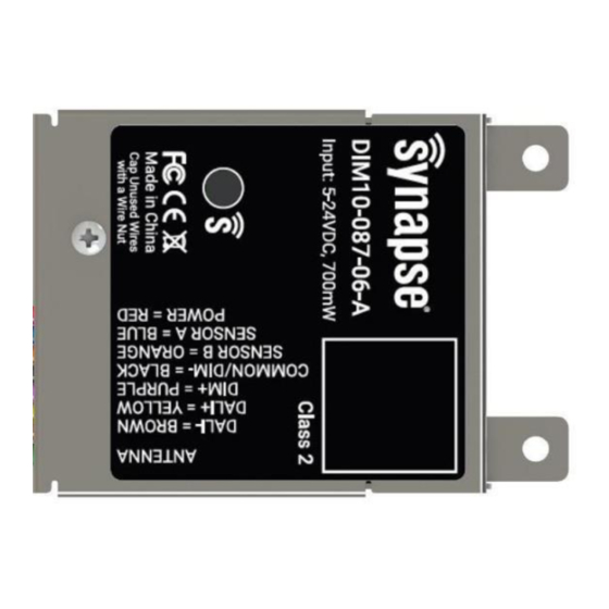
DIM10-087-06-A Controller
Load Ratings: 12 to 24VDC, +/-10%, 700mW max
Operating Humidity: 10 to 90%, non-condensing
WARNING AND CAUTIONS:
•
•
INSTALLATION GUIDE
Figure 1 - Proper Antenna Installation
NEEDED MATERIALS
•
Mounting Hardware: (2) #4 or M3 screws
recommended.
•
Antenna Kit: For available antenna options please
refer to our latest documents located on our
website.
www.synapsewireless.com/documentation
If you are unsure about any part of these instructions, consult an electrician; all
work should be performed by qualified personnel.
Disconnect power at circuit breaker or fuse when servicing, installing or removing
fixture or changing lamps.
INSTALLATION INSTRUCTIONS
WARNING: TO AVOID FIRE, SHOCK, OR
DEATH: TURN OFF POWER AT CIRCUIT
BREAKER OR FUSE AND VERIFY THAT POWER IS
OFF BEFORE WIRING!
MOUNTING
1.
Place the controller in desired location and secure
it using #4 or M3 sized screws using the mounting
holes located on the back edge of the DIM10-087-
06-A.
ATTACHING THE ANTENNA
2.
Make sure the power is off. When handling the
antenna cable, the technician must be grounded
with a proper ground strap.
3.
Remove red rubber dust cover, the washer, and
nut from the antenna connector.
4.
Determine the best location for external antenna
position and create an opening to mount the
antenna and bulkhead (See Figure 2 for
measurements).
5.
Feed the bulkhead through the opening in the
fixture. (Note: Recommended max thickness of
fixture wall is 6mm or 0.25 inches. This allows
enough threads on the outside of the fixture for a
good antenna connection.)
6.
Place the washer and the nut back on the antenna
connector and secure to fixture.
7.
Screw on the antenna hand tight. Tighten a 1/4
turn with a pair of needle nose pliers. Do not over
tighten or the RF pin in the bulkhead will crack,
creating poor RF link quality.
21-D08706A-INS A-5
Advertisement
Table of Contents

Related Manuals for Synapse DIM10-087-06-A


Summary of Contents for Synapse DIM10-087-06-A
- Page 1 DESIGN CONSIDERATIONS Below are some recommendations for successful dimming ATTACHING THE ANTENNA using the DIM10-087-06-A. The dimming control wires Make sure the power is off. When handling the are referenced as DIM+ and DALI-/COM. The dimming antenna cable, the technician must be grounded Figure 1 - Proper Antenna Installation signals have a Maximum voltage of 10V DC.
- Page 2 • Red = No Network Found (Communication Lost) Connect the (COMMON/DIM- = BLACK) wire from • the DIM10-087-06-A to the DIM- wire on the LED Blinking Green = Network Found, Controller Not driver. Configured (Device not yet added to SimplySnap) •...
- Page 3 Figure 3 - DIM to OFF Wiring Diagram WARNING: · If a single Synapse controller is used to drive the DIM+ input of multiple LED drivers, then all of the DIM- lines from all drivers MUST be directly tied/shorted together to provide a common return/ground to the controller.
- Page 4 Declaration of Conformity (FCC 96-208 & 95-19): REGULATORY INFORMATION AND Synapse Wireless, Inc. declares that the product name CERTIFICATIONS “DIM10-087-06-A” to which this declaration relates, meet the requirements specified by the Federal RF Exposure Statement: This equipment complies Communications Commission as detailed in the...
Need help?
Do you have a question about the DIM10-087-06-A and is the answer not in the manual?
Questions and answers